click on any pic to download a ~2MB huge a hi-rez photo
|
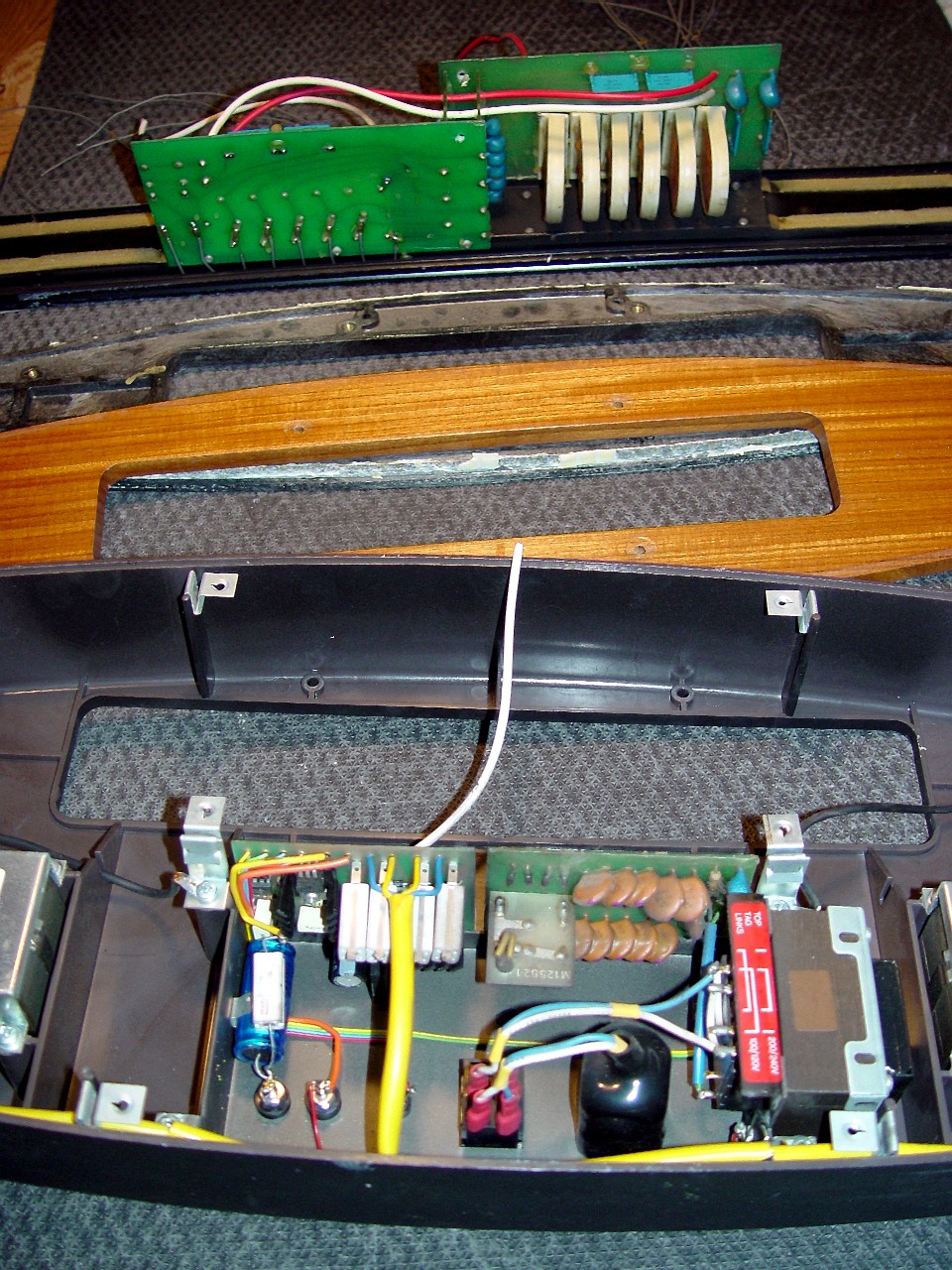
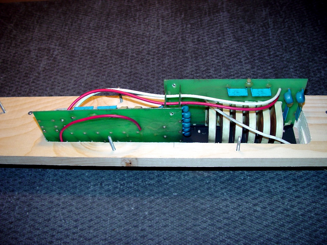
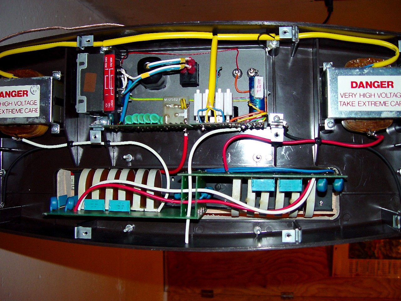
This image shows the components in the base of an ESL-63 after the panel assembly had been removed.
|
|
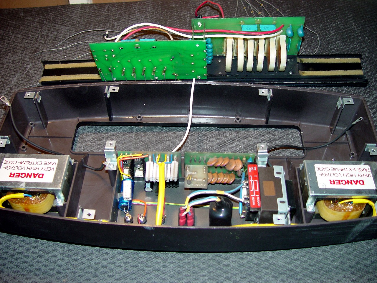
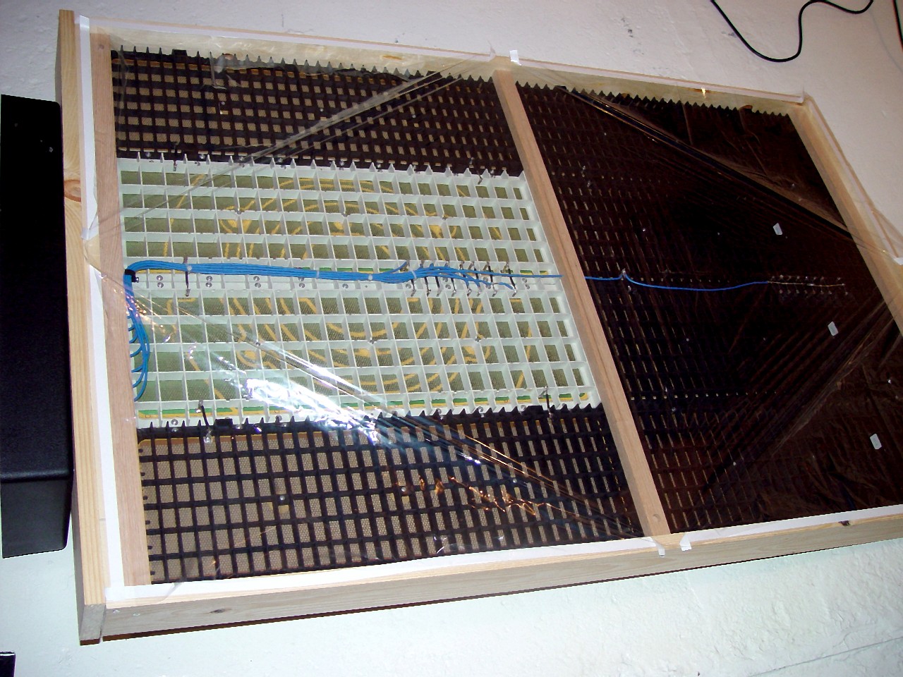
This image shows the plinth and the detached delay line of the ESL-63. It shows the bolt-hole protrusions for four of the eight bolts holding the plinth to the panel assembly. The preceding image shows the other four.
|
|

|
In this image, labels on the various wires show how the delay line and other components in the plinth of an ESL-63 interconnect. To separate the plinth from the panel assembly, turn the speaker upside down, and unscrew the baseplate from the bottom of the plinth. Despite all the electronics in the plinth, there are only four wires which connect the plinth to the panel assembly, and they are simple to remove and replace. The first wire is the coiled orange wire in the exact centre of the plinth. It exits the rectifier, and feeds high-voltage to the speaker's diaphragms via a hole drilled in the extruded metal base of the panel assembly. Cut this wire where it is soldered to the rectifier board. The second and third wires feed amplifier output to the delay line, via one wire from each of the two high-voltage step-up transformers. Cut both wires where they are soldered to the tranformers and remove the rubber plugs which hold them in place as they run from the transformers to the delay line. Wires connecting components in the plinth to the delay line have to be cut because the delay line is not attached to the plinth, but to the extruded metal base of the panel assembly. The fourth wire is the protection circuit's 'sniffer' wire. This is the white wire on the top of the delay line board. You cannot mistake this wire because it hangs loose at one end, ending in thin air. Because this wire is on top of, at right angles to, and in contact with, the high-voltage output wires, they generate sympathetic 'eddy currents' in it. If these eddies exceed a pre-set level, they signify to the protection circuitry that arcing may occur, and the amplifier input is immediately short-circuited. This sniffer wire feeds through two guide holes in the delay line assembly. Because it is free at one end, nothing needs to be cut or disconnected. The wire is simply pulled out of the guide holes. Replace it exactly as it was when re-assembling the speaker, or else the protection circuit will not function. Once these wires are disconnected, locate and unscrew the eight bolts holding the plinth to the panel assembly. The bolt-hole protrusions for four of the bolts are visible in this image. The following image shows the other four. Once all bolts are unscrewed, lift the plinth off the panel assembly. Follow the above procedures in reverse order to re-assemble the speaker.
|
|
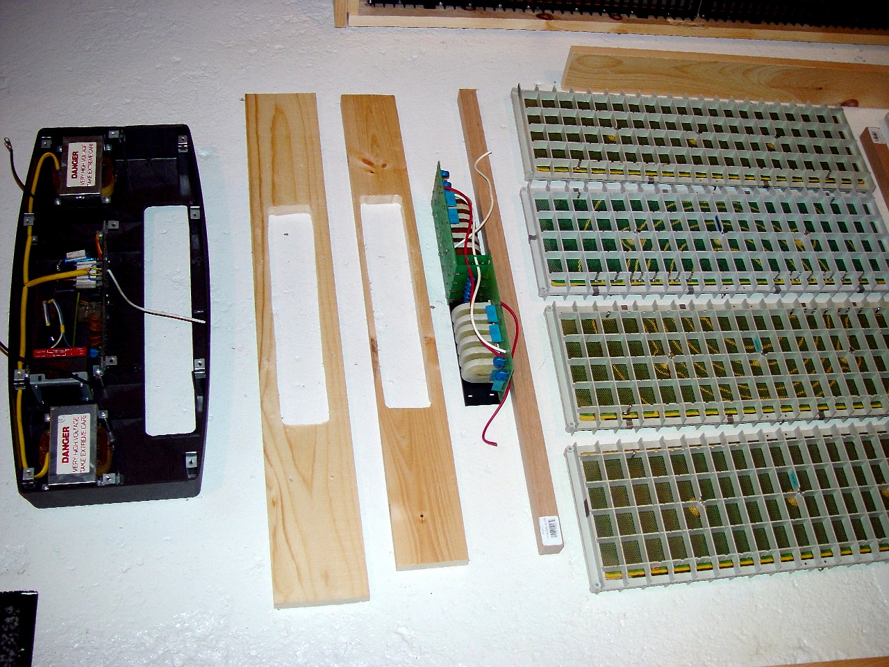
This image shows the ESL-63 delay line assembly after it has been removed. The wires exiting the delay line must be replaced by new wires, long enough to reach the stator panels in their new stacked orientation. The delay line will later be installed on top of the wood frame holding the stacked panels.
|

|
|
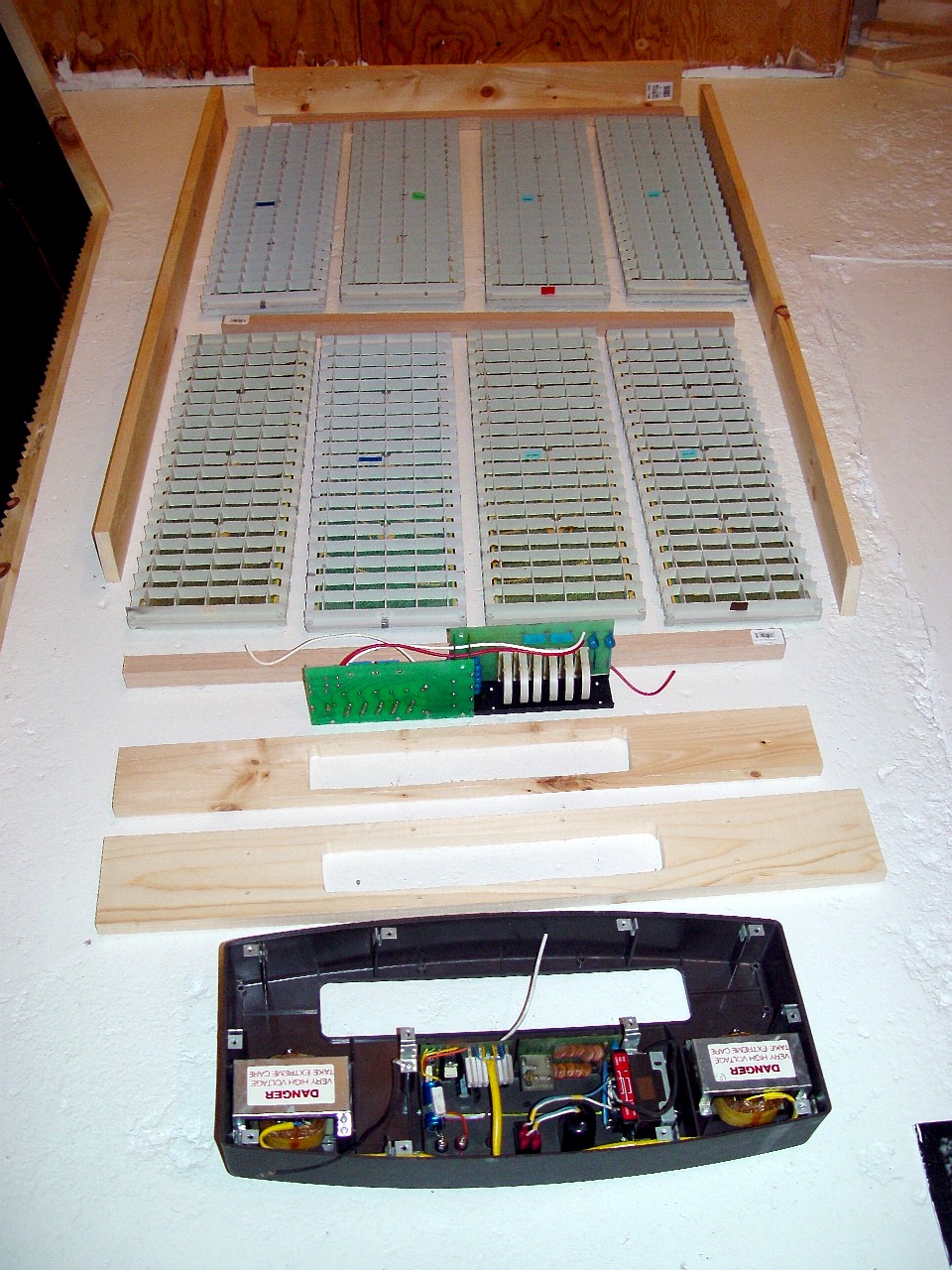
This image provides a head-on view of a pre-assembly mockup of the components of the stacked ESL-63. The frame is knotty pine softwood, nominally 4" by 1" and actually 3 1/2" by 3/4." The side-members of the frame are 50 3/16" long, while the top and bottom members are 32 1/2" long. Since the delay line is taller than the plinth, an additional top member is required, as a spacer. This top member is 31" long. Three cross-bars are required for each speaker, each 31" long. For the cross bars I use 1 1/16" square oak (hardwood) staircase railings. I have also used pressure-treated maple (hardwood) patio pickets, nominally 1" wide by 1.5" deep, and actually 7/8" by 1 3/8." The length of the side-members of the frame is affected by the thickness of the cross-bars you use.
|
|
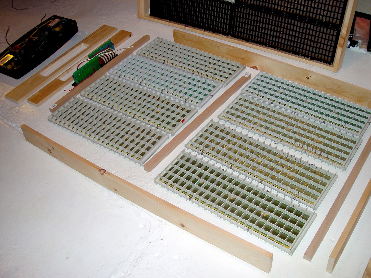
This image provides a side view of a pre-assembly mockup of
the components of the stacked ESL-63.
|
|

|
This image shows a pre-assembly mock-up the speaker in the foreground, and an assembled speaker in the background.
|
|
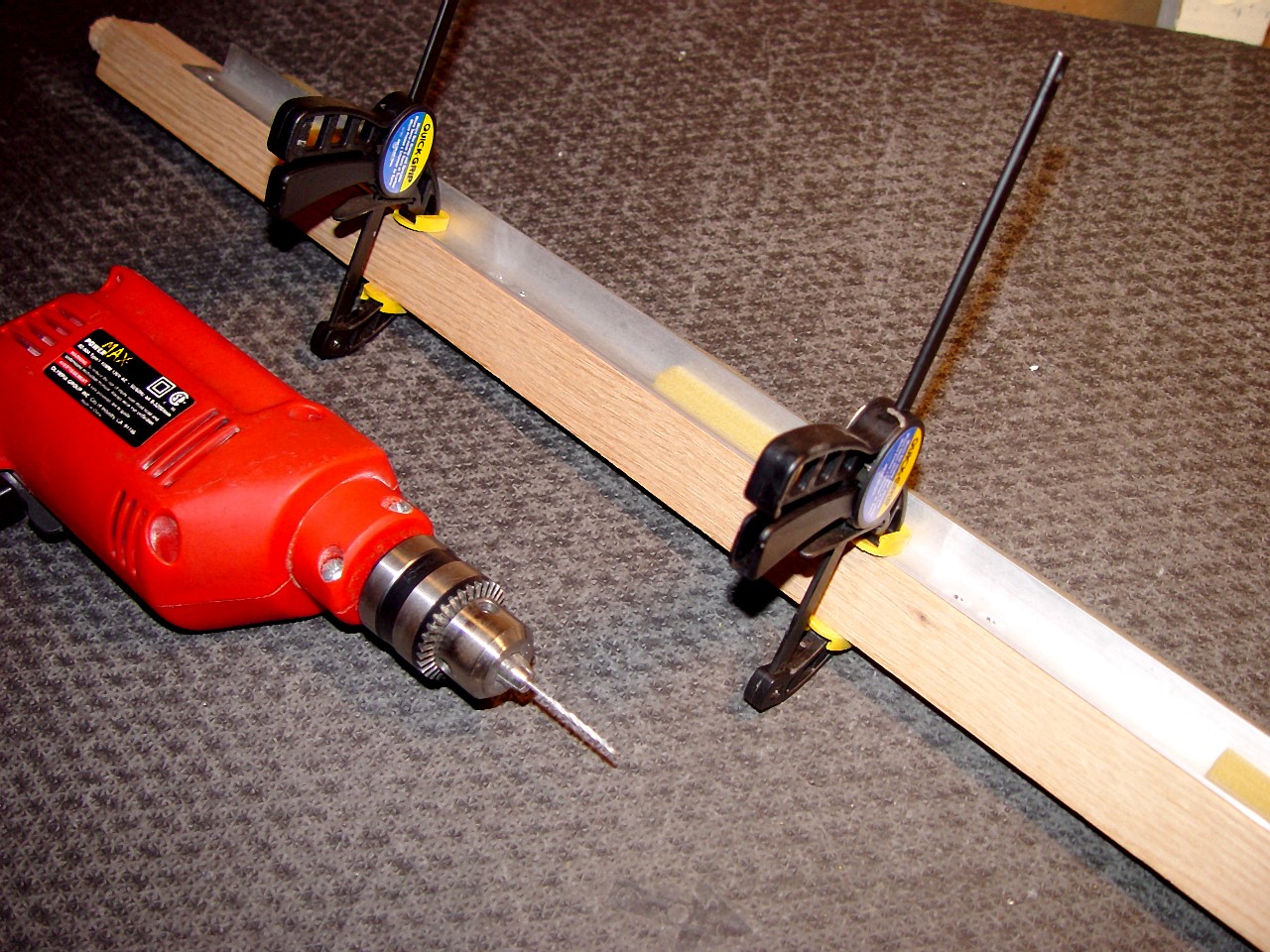
This image shows holes being drilled in the centre cross-bar to attach the stator panels. Use an ESL-63 panel assembly frame member as a template to locate drill holes exactly. With the template in place, drill the holes using a fine drill bit. Remove the template, and enlarge the holes to accommodate 1 1/2" #6 round head socket wood screws. Since the holes are only 7/32" from the edge of the wood, drill the holes to the exact size of the screw, so that the wood will not split.
|
|
|
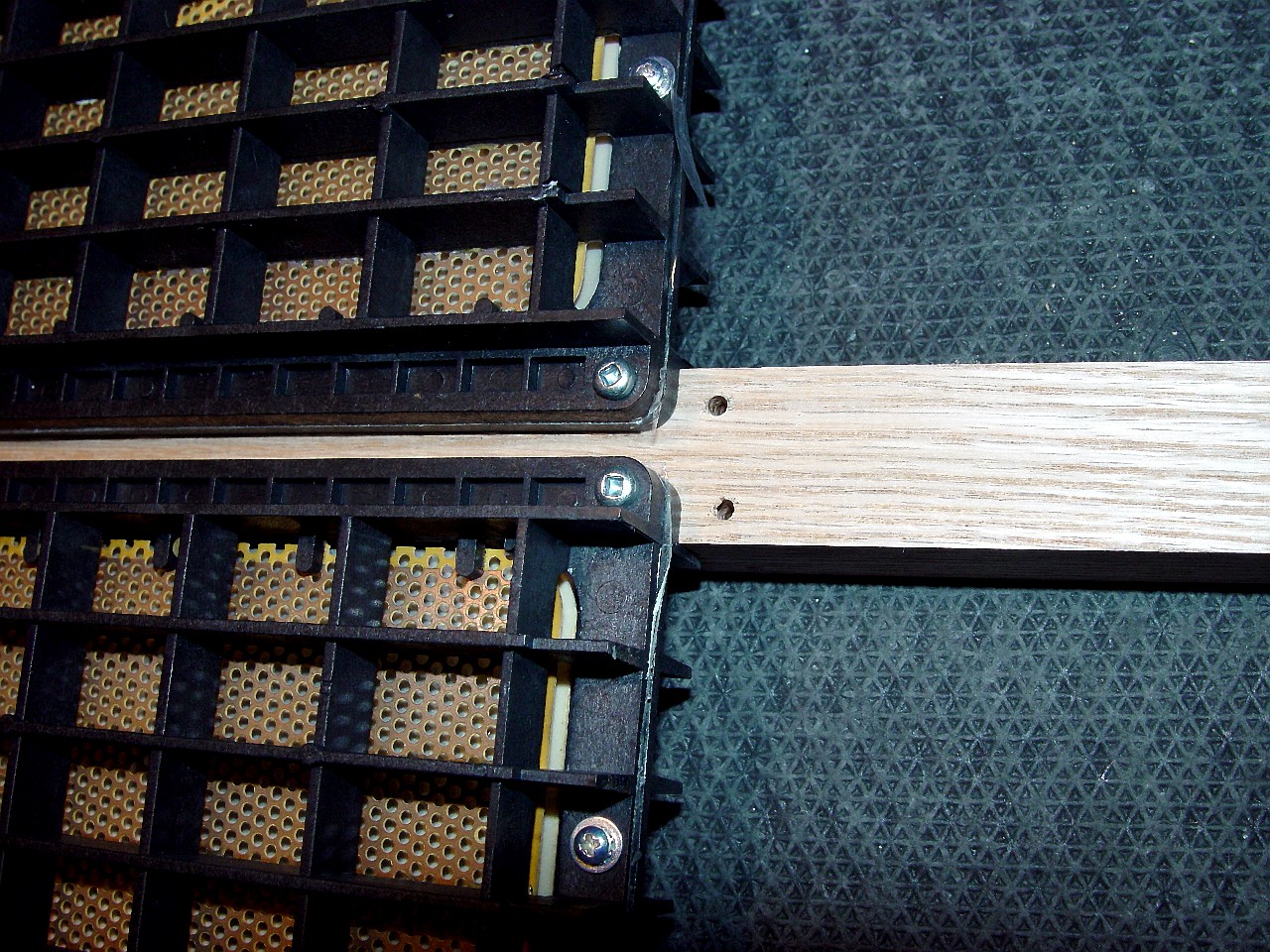
This image shows details of stator panels attached to the centre cross-bar of the frame. It shows two panels screwed to the cross-bar, and the drill-holes for the neighbouring panels. Use 1 1/2" #6 round head socket wood screws.
|
|
This image shows several stator panels attached to the centre cross-bar of the frame.
|
|
|
This image shows a pre-assembly mock-up of the top members of the frame with the delay line hole cut out. The delay line must be recessed, as otherwise it will not fit inside the plinth. Use an ESL-63 base plate as a template for the cut-out. Centre it on the frame, mark the cut-out and plinth bolt holes.
|
|
This image shows the top members of the frame with the delay line hole cut out. The delay line assembly sits in the cut-out, and is screwed directly on top of the top cross-bar of the frame. The bolts projecting attach the plinth to the speaker frame. They only pass through the upper of the two top members. Recess their heads to permit the two top members to be screwed flush together.
|

|
|
This image shows the delay line mounted on the cross bar of the speaker frame and projecting out of the top of the speaker frame. Use 3/4" #4 round head socket wood screws to attach the delay line to the cross bar.
|
|
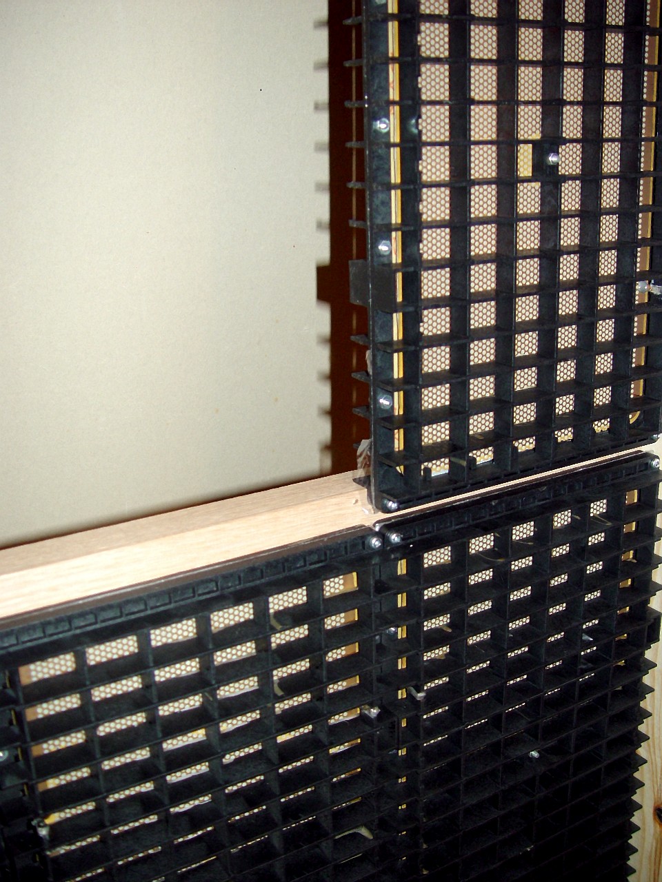
This image shows the top of two stacked ESL-63 frames. They are viewed head-on from the top. The two frames are standing on edge and side-by-side. The delay line is installed on the left frame, and is projecting out of the top of the speaker frame. The delay line is not yet installed on the right frame. On the right frame you can see two sets of drill holes. The first is to attach the delay line to the cross-bar. The second set of holes in the cross bar feed wires from the delay line to the front stator panels.
|
|
|
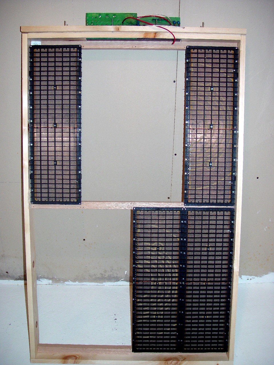
This image shows the assembled frame of the stacked ESL-63 with four of the eight panels installed. Set back the front of each of the three cross-members half an inch from the front edge of the speaker frame. Use 1 1/2," 2" and 2 1/2" #8 flat head socket wood screws to assemble the frame.
|
|
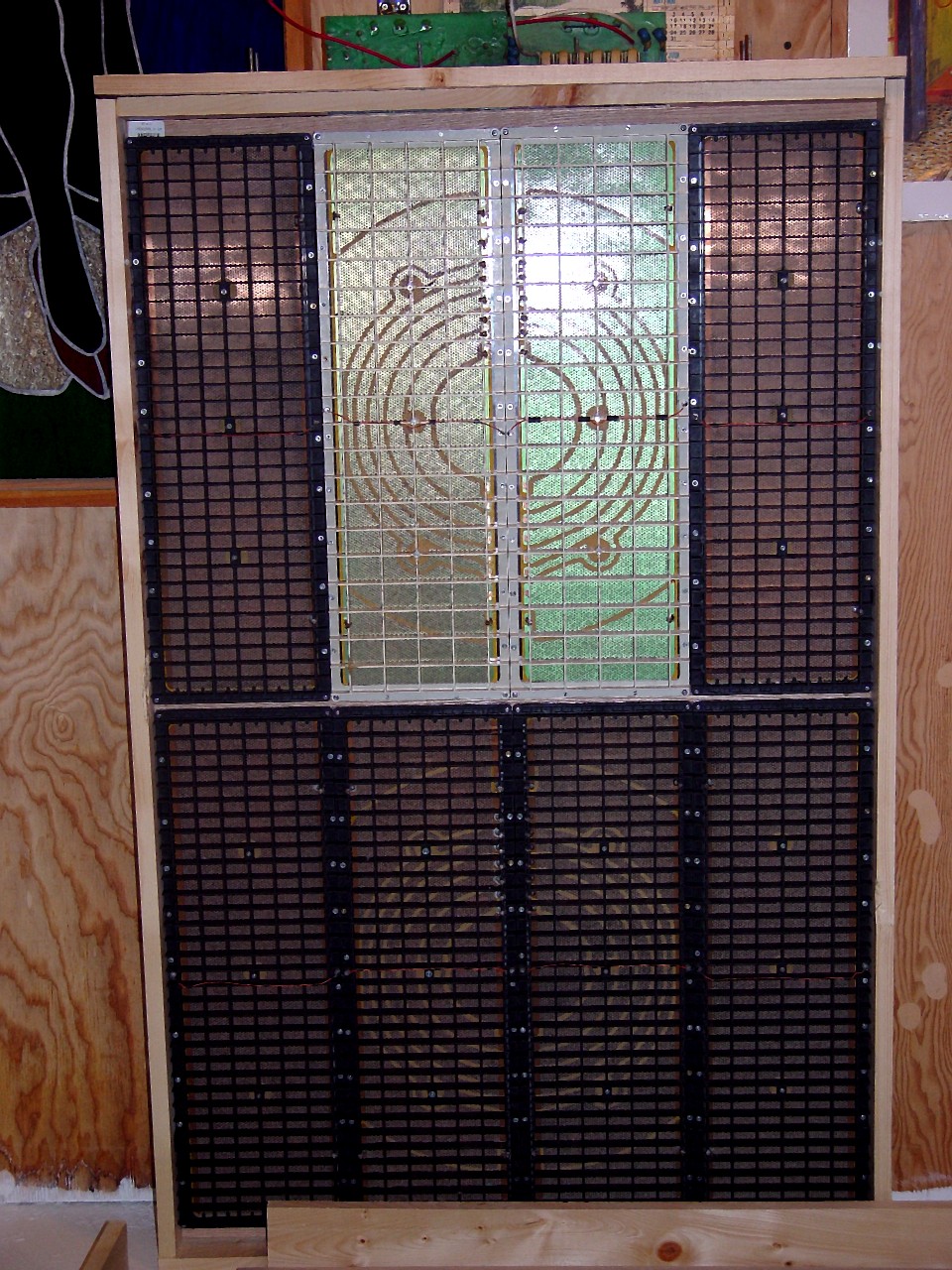
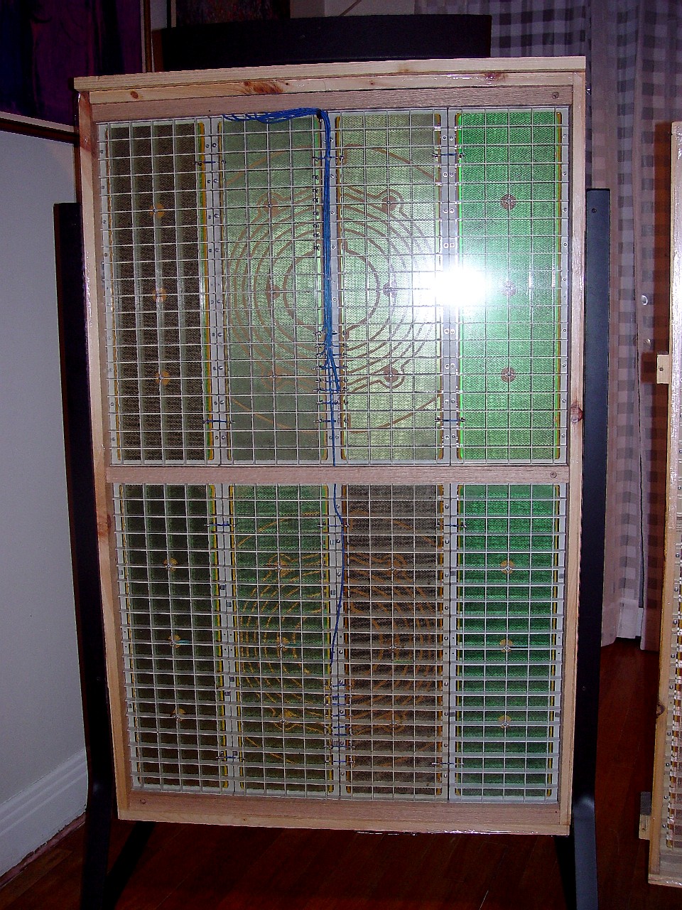
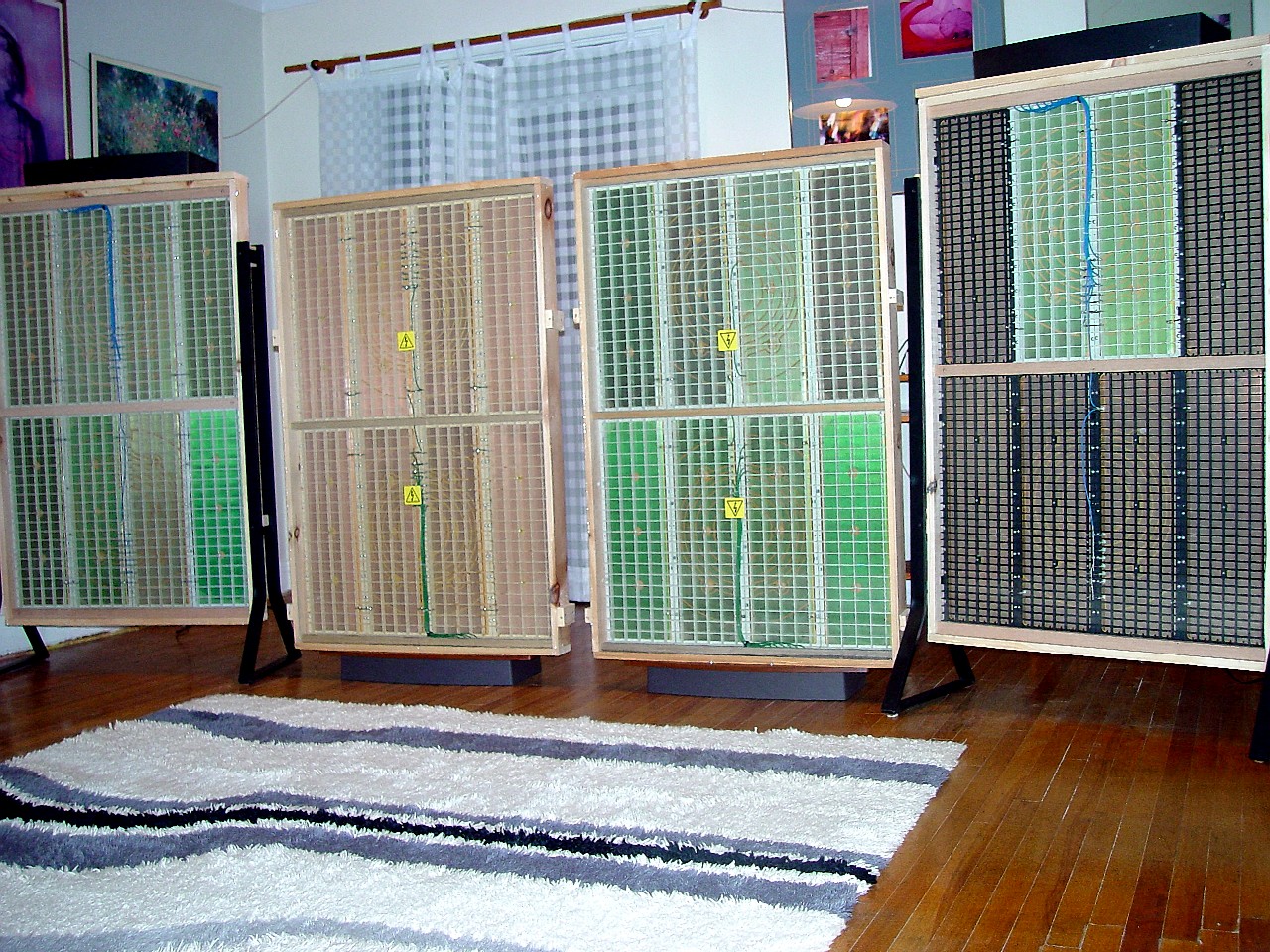
This image shows the speaker frame with all eight panels installed, prior to wiring. The upper white stator panels are from a USA Monitor, while the lower black stator panels are from an original-model ESL-63. This view is of the rear of the speaker, so the cross-bars are not visible.
|
|
|
This image shows a panel interconnect wire being soldered. I shield the cells adjacent to the wire with teflon-coated cloth to prevent solder splashes from damaging the diaphragm. A tiny drop of solder falling on to the diaphragm tends to partially melt the diaphragm, and to bond to it. This miniscule and barely visible blob of solder sitting on the diaphragm reduces the stator-to-diaphragm gap. As a result, the speaker will almost certainly fail. There are 104 cross-wires on a stacked ESL-63. A single solder splash will oblige you to invest countless hours searching for the cause.
|
|
This image shows all wires soldered to the master set of panels. The stacked ESL-63 incorporates modifications to the delay line assembly so as to take full advantage of the four extra panels. The first modification is to bridge the two outermost segments of the upper four 'master' panels, and to feed them from the seventh delay line. You can see the bridge on the two outermost contact points on the stator panels. The second modification is to feed the eighth delay line exclusively to the four lower 'slave' panels. This significantly increases the radiating area driven by the seventh as well as the eighth delay lines, the lines producing, respectively mid-bass and extreme bass. While the panels have eight concentric circles, there are only six delay lines - there is no delay in the feed of the output to the two outermost concentric circles. The reason for this, I believe, is that while the ear can spatially locate high-frequency sounds well, it cannot do so with low frequencies. Hence there is nothing to be gained by delaying output to the two outermost concentric circles, as they contain only low frequency information. In that there is no delay in output to the two outermost concentric circles, this alteration to the ESL-63 wiring does not violate the integrity of Quad's concentric circle delay line.
|

|
|
This image shows how the two outermost segments on the 'master' stator panels are bridged. The two outermost stator panels now reproduce midrange as well as bass output.
|
|
This image shows how all segments on the 'slave' stator panels are bridged. All segments of all four 'slave' panels are driven from the end of the delay line of the four 'master' panels, to preserve the integrity of Quad's concentric circle delay line. The four 'slave' panels now reproduce the output previously assigned to the two outermost panels in a normal ESL-63.
|
|
|
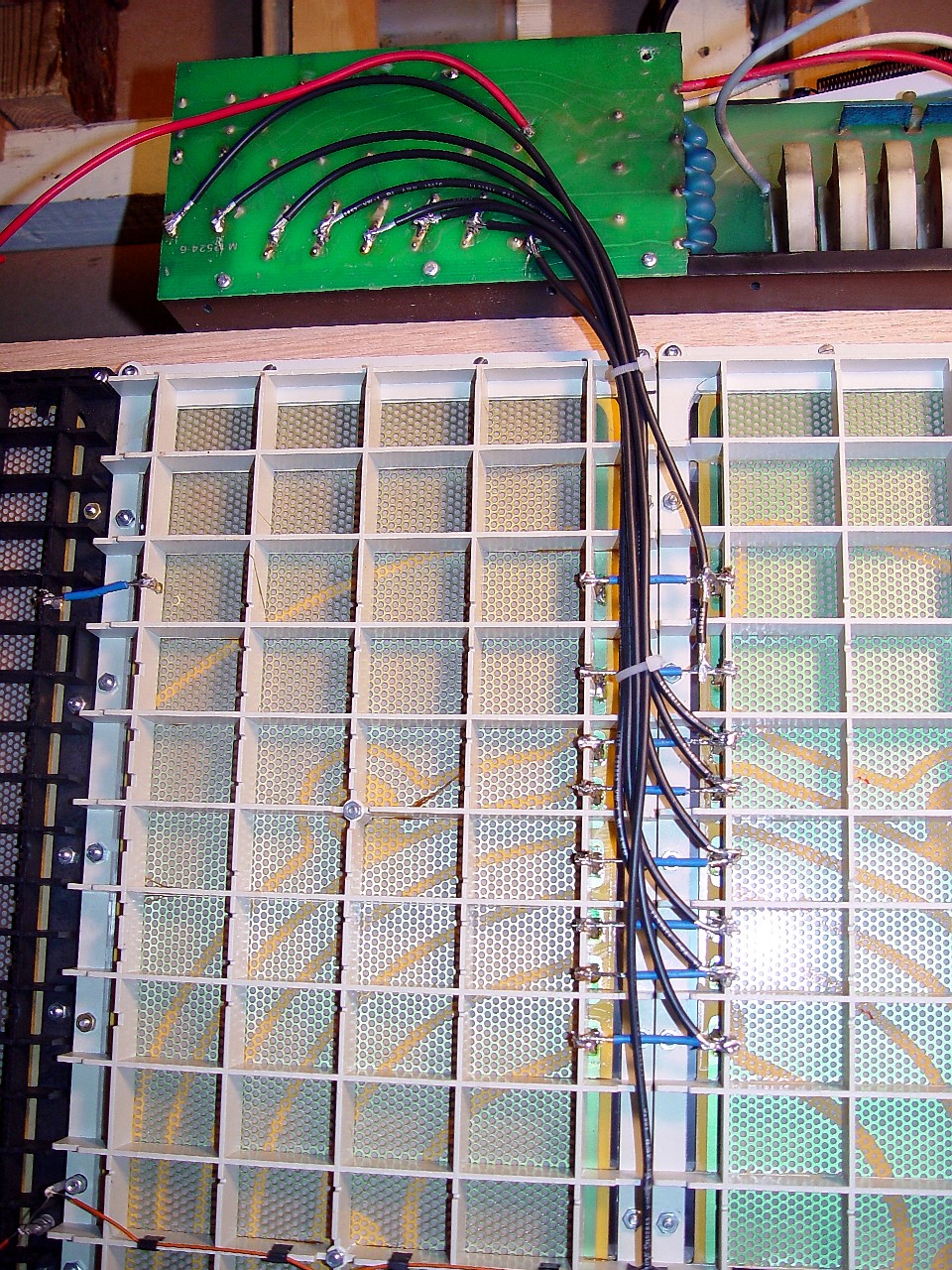
This image shows all wires soldered to the panels and to the delay line assembly on the front of the speaker. The two top frame members have been removed to simplify feeding and soldering panel-to-delay line wires. The front and rear delay assemblies are identical. However, the way in which front wires run from the delay line assembly to the panels differs from the rear of the speaker, since the cross-bar is in the front of the speaker. The rightmost wire from the delay line assembly feeds the centre (innermost) segment of the centre stator panels. The next wire feeds the next segment, and so on. Do not mis-align wires. Insert aluminium foil or teflon-coated cloth between the connection being soldered and the stator panel, to avoid solder splashes ruining the diaphragm.
|
|
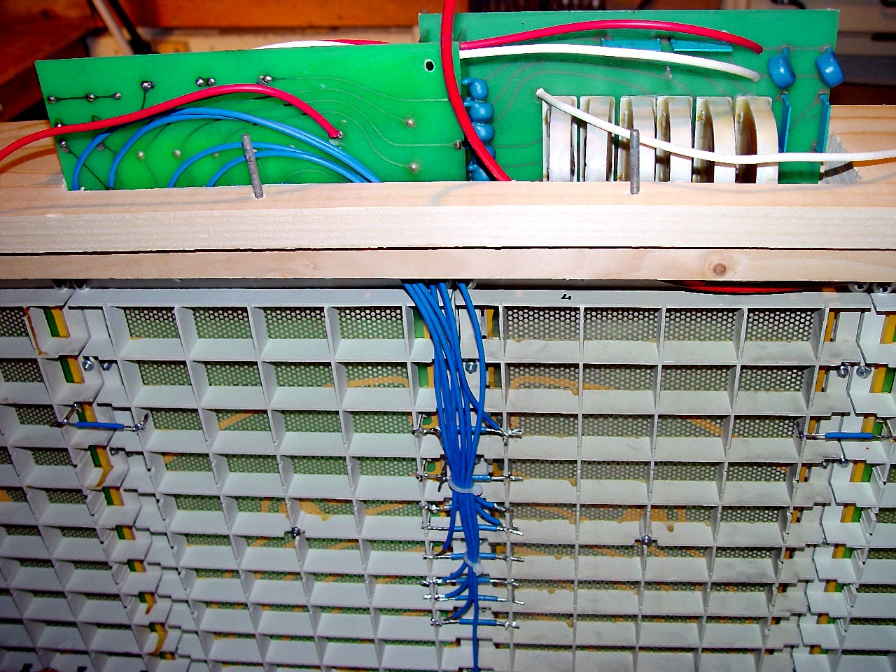
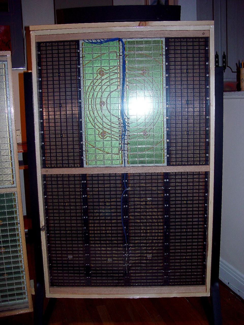
This image shows all wires soldered to the panels and to the delay line assembly on the rear of the speaker. The two top frame members have been removed to simplify feeding and soldering panel-to-delay line wires. The front and rear delay assemblies are identical. However, the way in which rear wires run from the delay line assembly to the panels differs from the front of the speaker, since there is no cross-bar in the rear of the speaker. The eight wires exiting the delay line assembly feed output sequentially to the eight concentric circles of the rear stator panels, beginning with the centre (innermost) circle. The rightmost wire feeds the innermost concentric circle. The next wire feeds the next segment, and so on. Do not mis-align wires. Insert aluminium foil or teflon-coated cloth between the connection being soldered and the stator panel, to avoid solder splashes ruining the diaphragm. The delay line assembly performs a dual purpose. The first is to feed the output sequentially to the various concentric circles so as to give the impression that the sound comes from a virtual point-source behind the speaker's panels. The speaker does this with uncanny realism. The second purpose is to use the segmentation of the stators so as to assign extreme high-frequencies exclusively to the innermost concentric circle, and to progressively filter out more high-frequency output with each successive concentric circle, so that the outermost concentric circle reproduces only bass frequencies. The intent behind this is to improve the speaker's high-frequency dispersion. If high-frequency output were reproduced by the entire radiating area of the panels, it would 'beam,' and the ideal listening area would be extremely narrow. By limiting high-frequency output to the small centre portion of the panels, dispersion is much wider. Only high-frequency output is filtered. Bass output is produced by the entire radiating area of the speaker, even the innermost circle.
|
|
|
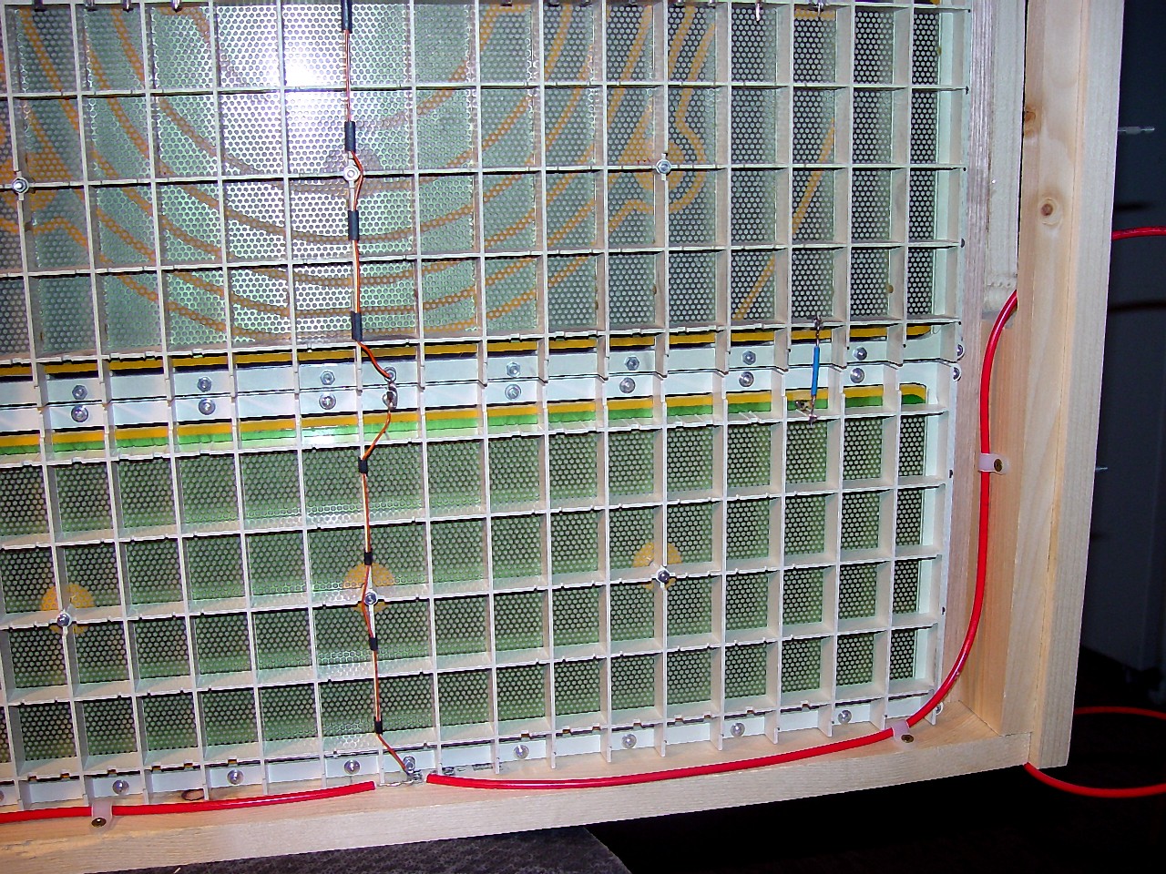
The high voltage (red) wire runs around the perimeter of the frame. It feeds high-voltage from the rectifier in the plinth to the diaphragms of all eight stator panels. The rectifier is capable of keeping eight panels charged.
|
|
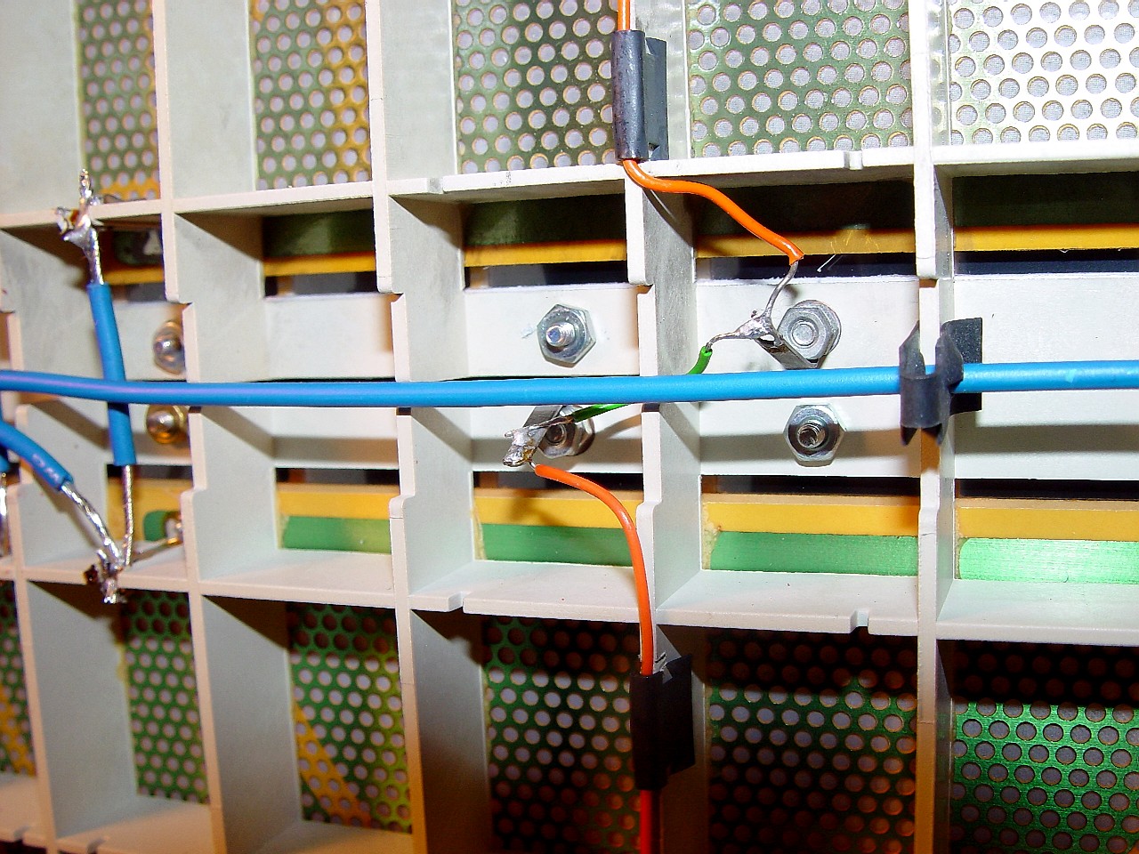
Because of the way the panels are installed, only the final (eighth) signal-carrying wire from the delay line comes close to the EHT wire. Note how this wire and the EHT wire are arranged so as to avoid contact. The green wire interconnecting the EHT wires of the two panels feeds beneath the bass panel wire, which is held in place by a guide clip.
|
|
|
This image shows the speaker with all panel and delay line wire inter-connections made, just prior to installation of the plinth on the frame.
|
|
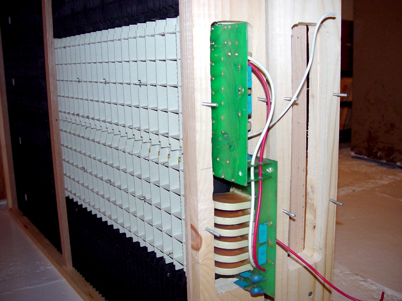
This image shows the plinth installed on the frame. The plinth is on top of the frame rather than on the bottom to minimize wire length to the upper 'master' panels. I use a stock ESL-63 plinth. Its protection circuit triggers when it senses a load which would damage a single ESL-63. Although stacked ESL-63's can take more bass input than a stock ESL-63, they can still arc at the same input level if the input is primarily treble or mid-range. Nonetheless, because they produce so much bass and mid-range without strain, they give an impression of producing higher SPL/bass.
|
|
|
This image shows a dustcover being installed on a stacked ESL-63. Images and instructions elsewhere on this site explain how to ensure evenly tensioned dustcovers. Note that the film is first attached to the centre point of each side, and pre-tensioned. Then the film in each of the four quadrants of the speaker is tensioned separately. After that, heat-shrink the film with a hair dryer to remove any remaining creases.
|
|
This image shows a completed stacked ESL-63. While stacked ESL-63's produce more and deeper bass, what is noticable is the increase in "body" in the mid-range. This seems to enhance treble performance, effortlessly producing music with weight to it over the entire frequency range. The speakers were demonstrated to the Montreal Audiophile Association, and filled a room 50 by 30 by 9 containing over 50 persons. Their opinion was that the performance was outstanding, with no bias toward a particular frequency. As usual, listeners new to electrostatics raved over the clarity, and it was this that they commented upon, not the bass.
|
|
|
This image shows another completed stacked ESL-63. The two white panels are USA Monitor stator panels. The remaining six black panels are original ESL-63 stator panels. The difference in cell-spacing between the two stator panels is obvious. While the USA Monitor stator is more open, it is also less rigid. I can hear no difference between the two.
|
|
The justification for a stacked ESL-63 is simple. The ESL-63, ESL-988 and ESL-989 use identical and interchangeable stator panels. An ESL-989 costs about $13,000 Cdn, and has two panels fewer than a stacked ESL-63. Two pairs of ESL-63's can be bought for about about $4,000 Cdn, and as these images show, building your own stacked ESL-63's may be complicated, but it is not rocket science.
|
|