Quad ESL-63 repair by Hey You
click on any pic to download a ~2MB huge a hi-rez photo
Quad ESL-63 repair by Hey You
click on any pic to download a ~2MB huge a hi-rez photo
|
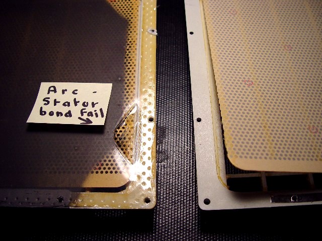
This image shows the top and bottom halves of an ESL-63 panel opened like a book. On the rear half of the panel (on the right), the bond between the stator and its egg-crate grid has failed, and the stator has curved upward. On the front half of the panel (on the left), there is an arc-hole burnt in the diaphragm due to contact with this unbonded stator.
|
|
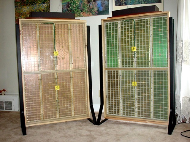
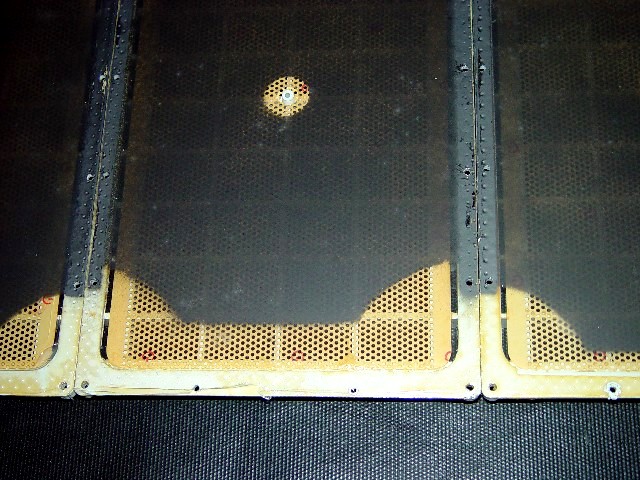
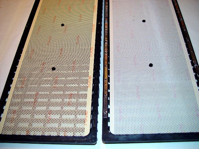
This image shows the diaphragms on three separate ESL-63 panels. On the left and right panels, the uncoated and inert portion of the diaphragm at each end of the panel is three eighths of an inch wide. However, on the centre panel, this gap is seven-eighths of an inch wide. Thus the centre panel sacrifices one linear inch (one half inch at each end of the panel) of driving area compared to the panels on either side of it. This extra inert portion of the diaphragm reduces the likelihood that the diaphragm will fail if the stator bond fails. However, it also reduces the effectiveness of the speaker. Perhaps this larger gap signifies that Quad was aware that it had a stator bond failure problem. I have measured a gap of five eighths of an inch on other panels. For whatever reason, Quad altered this gap on various panel batches.
|
|
|
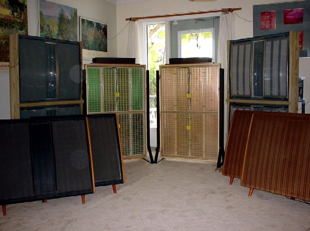
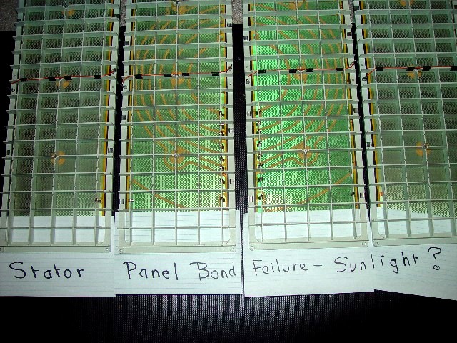
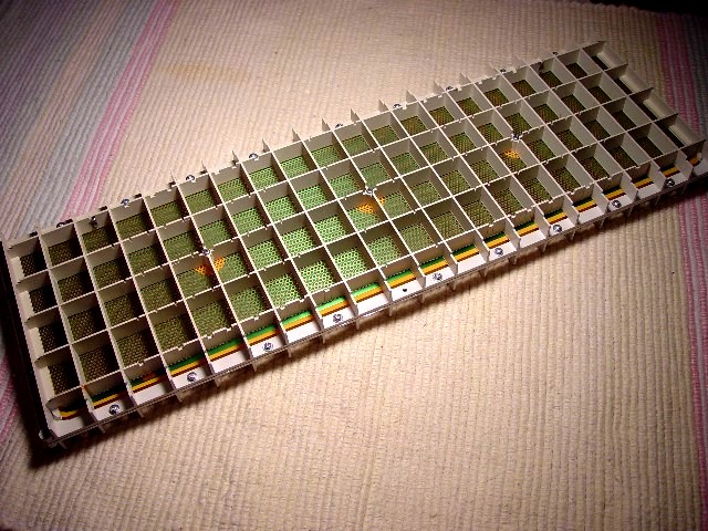
This image shows the four panels as they would have been in the speaker. I have slipped sheets of paper between the stator and the grid to show where the bond has failed.
|
|
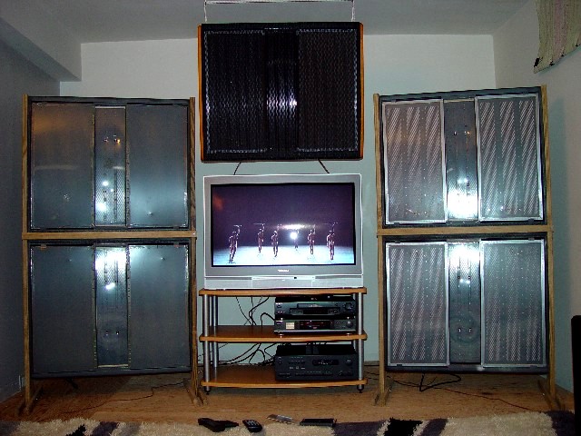
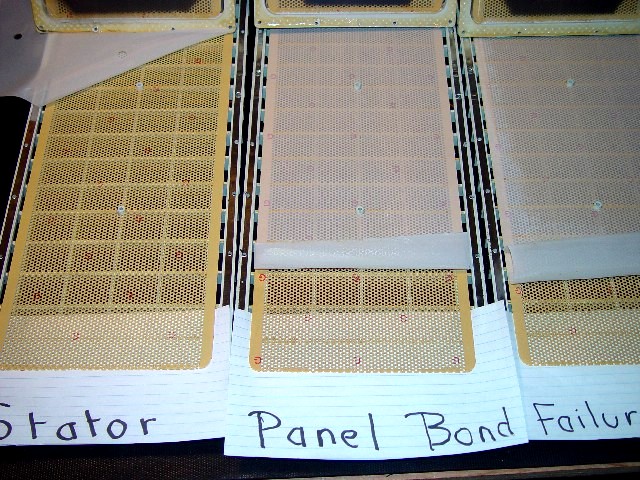
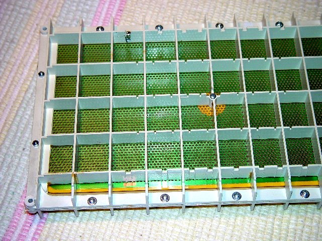
This image shows the same four panels as seen from the interior. I have peeled back the nylon damping material slightly further than the separation, so as to re-bond the stator and grid. This gives an idea of the degree of failure. One end of the rear stator on each panel was actually touching the diaphragm. Because the outermost five eighths of an inch of the diaphragm is uncoated and has restricted movement, the speaker played well at low volumes. Nonetheless, arcing would occur at an amplifier input level well below what the speaker was designed to accept.
|
|
|
This image shows front and rear stator panels, with the diaphragm (which attaches to the front panel) removed. When the front and rear panels are bolted together, the aluminium foil along the long edges of the rear panel contacts the coated side of the diaphragm and transfers the high-tension charge to it. Note the nylon damping material which is on the rear panel but not on the front. The damping material is like the sheer nylon used for stockings and is glued to the stator panel. Note also the three centre-panel spacer bolt protrusions.
|
|
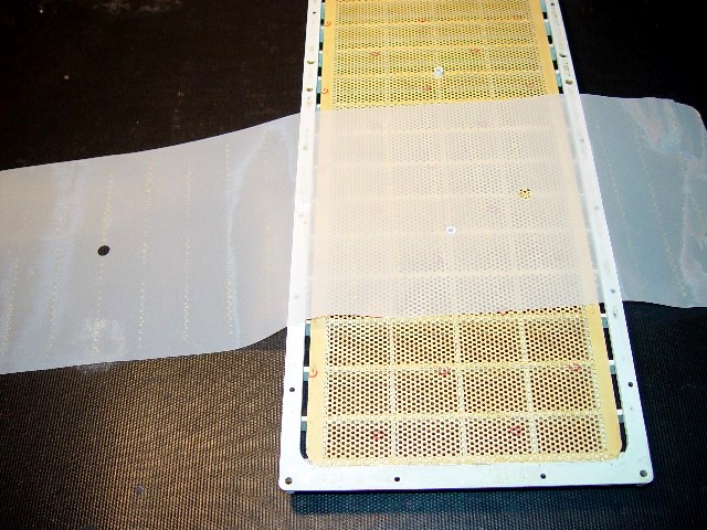
This shows the nylon sheet used by Quad to damp diaphragm resonances. It is glued to the interior of the rear stator panel. The nylon is about twice as coarse as that used in pantyhose. Apart from this damping sheet, the front and rear stator panels are identical.
|
|

|
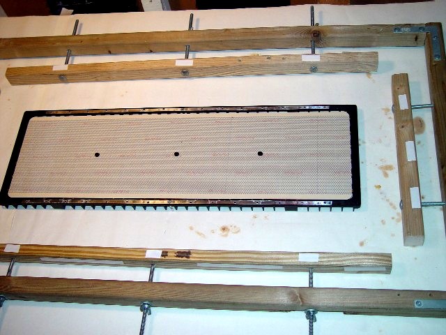
This shows a stator panel (the thin, copper coated perforated plate) being re-glued to its supporting structure (the egg-crate cage). The bond between these two fails quite frequently, usually at the outside edges. Because the stator panel is so thin, it bends upward, contacts the diaphragm, which then arcs until it is destroyed.
|
|
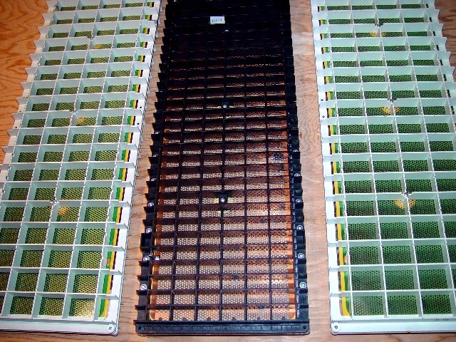
This image shows an early Quad panel alongside the later USA Monitor panels. The USA Monitor panel is actually less rigid (but acoustically more open) than the panel it supplanted.
|
|
|
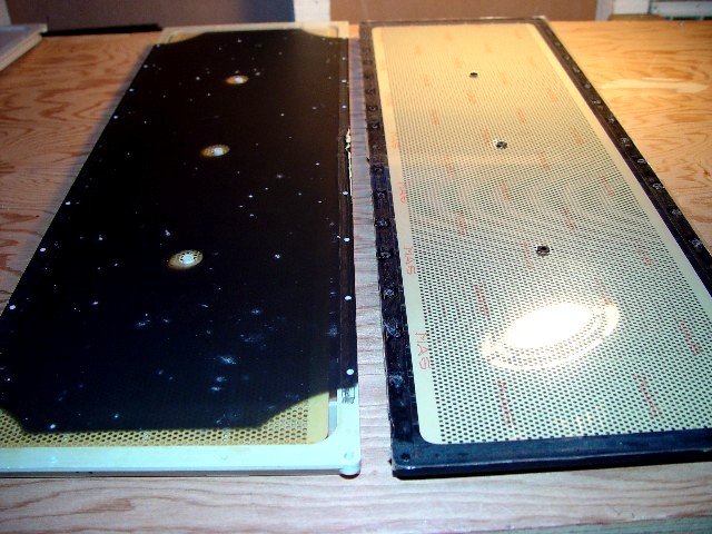
This image shows an original Quad diaphragm alongside a rebuilt panel. The white spots on the dark coating of the Quad diaphragm are where the coating has apparently turned to ash, due to arcing. The coating on my diaphragms is transparent. Diaphragms are not coated at their outside corners. This is to avoid contact between the charged diaphragm and the screws at each corner of the panel which fasten the panel to the panel assembly (and to ground).
|
|
This image gives a close-up of two damaged panels. In the first, the bond between the stator panel and the diaphragm has failed. In the second, the diaphragm is ripped immediately adjacent to the point of bonding to the panel, apparently due to fatigue.
|

|
|
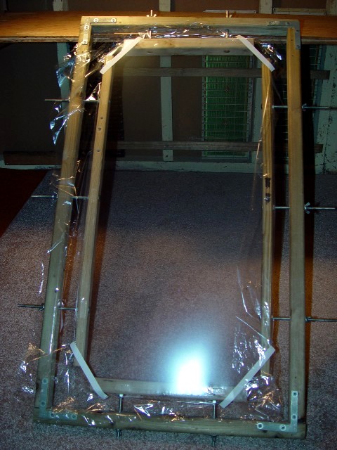
This image is of the mylar stretching jig. The white strips on the inner frame are double-sided tape. Tape is placed on the top of the jig (aligned with each bolt), and on the side. The tape's backing is not peeled off until the mylar is about to be attached. The tape on the top of the jig simply pre-stresses the diaphragm. The mylar is laid over the top of the jig, and these "pre-tensioning" tapes are then detached and re-attached until the diaphragm is evenly tensioned. After this, the mylar is applied to the side tape. The tape's holding ability is extremely strong because the mylar is wrapped around the edge of the frame. Tensioning the mylar pulls it more tightly onto the tape rather than off it, and the grip of the tape is reinforced by the friction of the mylar on the wooden frame of the jig frame.
|
|
This image shows a three micon mylar diaphragm fully-tensioned. A micron is one millionth of a metre. Thus the ESL-63 diaphragm is one three-thousandth of a centimetre thick, so thin that it is like gossamer. I tension the mylar very slowly and cautiously, turning each wing-nut a half turn at a time, until the mylar is tensioned almost to the point of failure. It tears very easily, and fails completely.
|
|
|
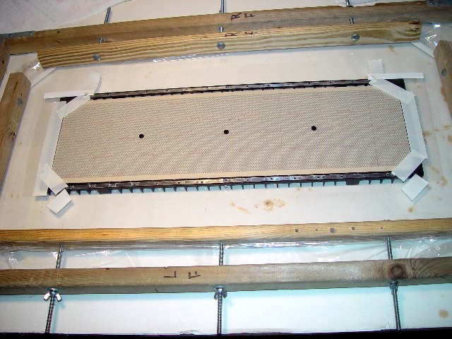
In this image, the diaphragm is resting on a stator panel to be masked prior to being coated. The purpose of the acetate cut-out mask taped at each end of the panel is to prevent any diaphragm coating being deposited on the outside corners of the panel, where it is connected by screws to the aluminium panel assembly. Although the diaphragm is fragile and tears extremely easily, it can nonetheless support the weight of the jig.
|
|
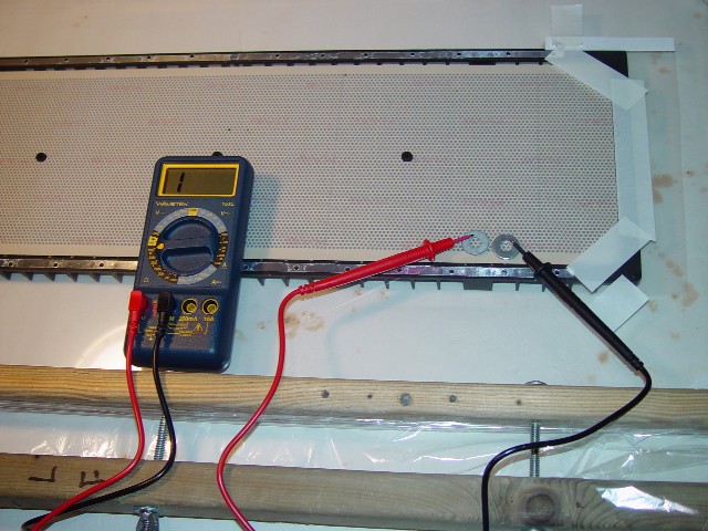
In this image, the resistivity of the diaphragm coating is being tested. Unlike the Quad diaphragm coating, my coating is transparent. I place washers about a quarter of an inch apart and touch a probe to each one. I cannot put the probes directly to the mylar as they would pierce it and cause it to fail. A resistivity reading of 200 megohms or higher is sufficient for a panel to reproduce all frequencies without charge migration. The multimeter in the image is set to read resistivity of 2,000 megohms, and the reading on the screen indicates that the resistivity is too high for the meter to read. The resistivity of the original Quad diaphragm coating is about one million megohms.
|
|

|
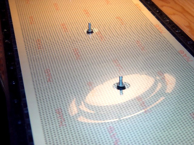
This close-up image shows the stator panel spacer bolts projecting through holes pierced in the diaphragm. Spacer bolts are needed down the centre of the panel to preserve an exact stator-to-diaphragm gap over the ESL-63 panel's entire span.
The holes are just large enough to ensure that the bolts and the panel protrusions do not impede diaphragm movement. At high volumes, air resists being moved by the diaphragm, and tries to escape through these spacer holes. This makes no sound when the diaphragm is made of three micron mylar. However, if an ESL-63 diaphragm is made out of thicker material (for instance the 12 micron mylar used in ESL-57 treble panels, or the Saran used in ESL-57 bass panels), you will hear unpleasant candy wrapper or bodily function noises as the force of the air squeezing through the holes causes the diaphragm in the area of the holes to vibrate loudly. |
|
In this image, the front panel is bonded to the diaphragm.
|

|

|
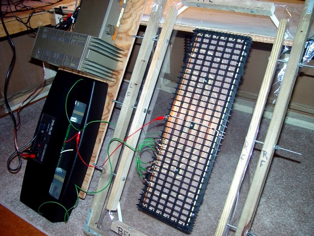
In this image, the front and rear panels have been partially bolted together. Note that holes for reinforcing bolts have been drilled in each alternating cell around the panel perimeter, forming a final assembly that is significantly more rigid than a stock Quad panel. The panel is tested while it is still in the stretching jig. I drive the single panel directly from the output of the plinth's step-up transformers, using an ESL-63 plinth which is stock except for removal of delay line circuitry. I use a 45 watt 303 amplifier. Driving a single ESL-63 panel with this amplifier corresponds to driving all four panels of an ESL-63 with an 180 watt amplifier. The plinth's protective circuit will not trigger, as it is calibrated for a four-panel load. When testing a treble panel, I use eight-head jumper cables in order to bridge all eight segments, so that the entire panel runs full-range.
|
|
This image shows a rebuilt panel with reinforcing bolts installed around the perimeter.
|
|
|
This image shows a close-up of reinforcing bolts on a rebuilt panel. Note that the heads of the bolts on the ends of the panel have been reversed vis-a-vis those on the sides of the panel. This is to prevent contact between the end bolts and the metal extrusion to which the four panels are bolted.
|
|
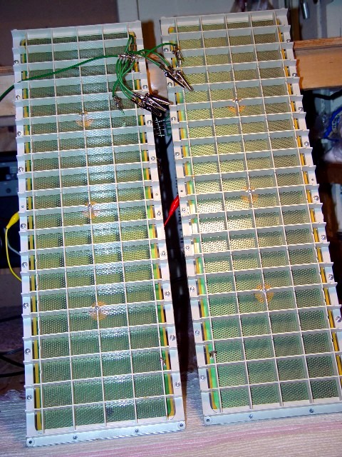
This image shows two reassembled panels receiving a 24 hour test prior to being returned to the client.
|
|