click on any pic to download a ~2MB huge a hi-rez photo
click on any pic to download a ~2MB huge a hi-rez photo
|
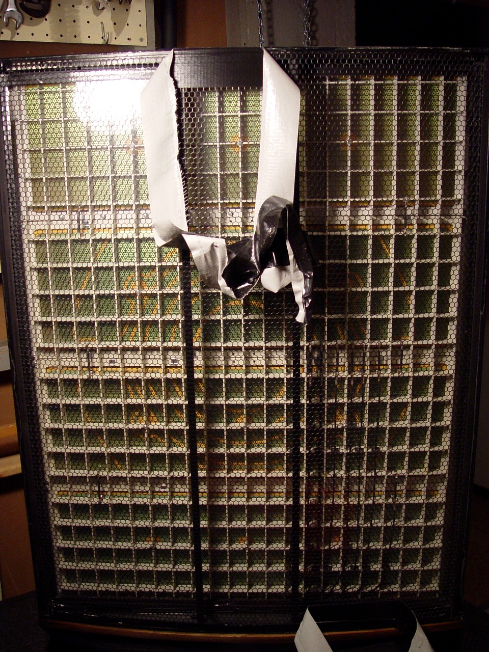
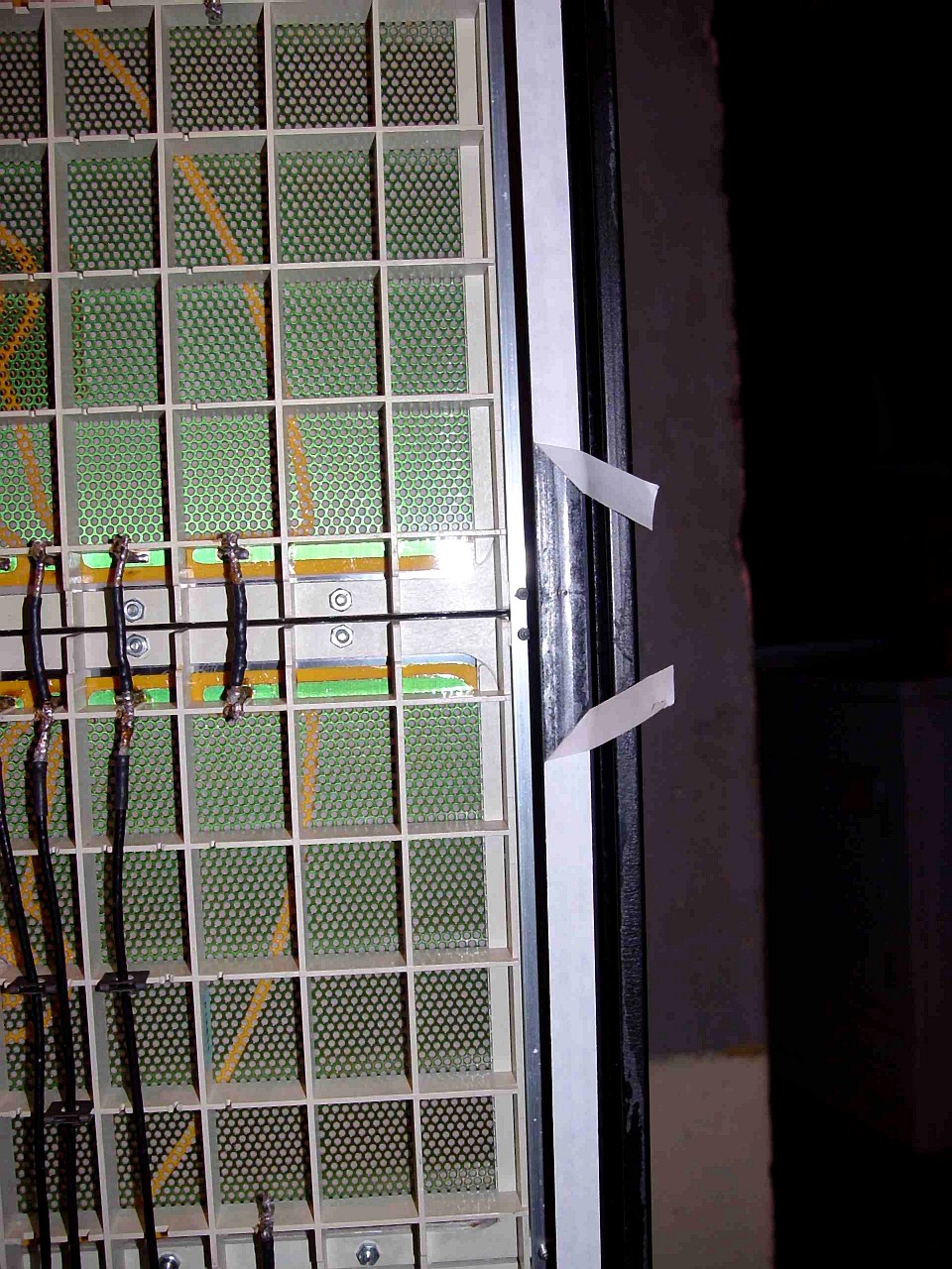
This image shows the ESL-63 grill with the tape holding it to the speaker frame partly removed. This tape holds the grill against the frame of the ESL-63 so that it does not vibrate. In order to remove the grill, the sock must be pulled down so that it is stretched over the plinth. The wooden top is removed by sliding it to one side, and the sock is lowered by unpeeling it from the Velcro stapled to the top of the speaker frame beneath the wooden top. Over time the grill tape hardens and dries, and dust may flake off as it is removed. If this occurs, vacuum clean thoroughly, so as not to subsequently contaminate the stator panels. Once the tape has been removed, pull the metal grill out of the speaker frame. Hold the grill at top and bottom centre, and pull gently until it pops out of slots in the extruded metal frame. At the base of the grill is a spring clip which earths the grill to the rest of the speaker. Occasionally his clip catches in the grill's perforations and complicates removal.
|
|
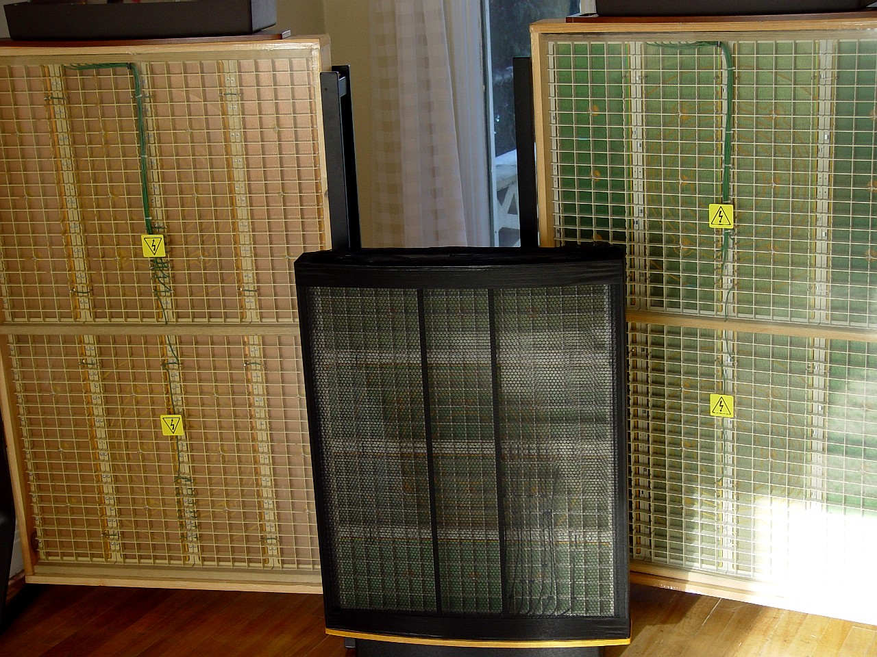
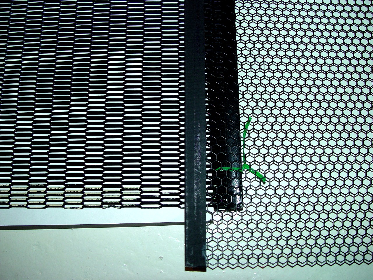
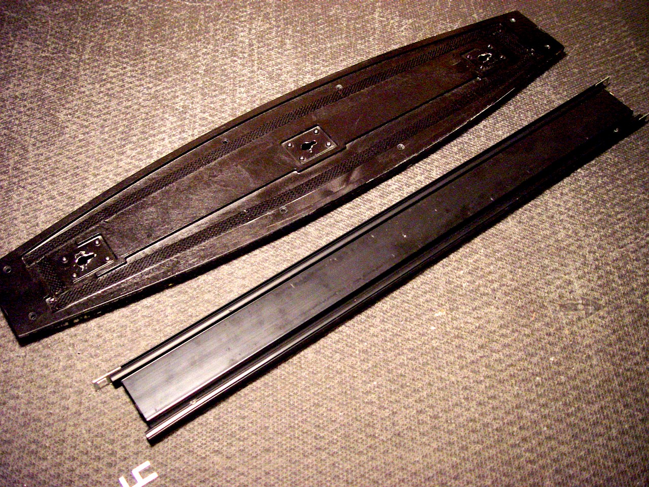
This image shows the grill of the Crosby ESL-63 after it has been removed, alongside the grill of a standard ESL-63. The purpose of the duct tape around the edge of the grills is to tighten the fit of the grill in its slot in the extruded metal frame of the ESL-63, so that it does not vibrate. Since the Crosby grill is considerably thinner than a stock grill, it does not fit as tightly, and so is more disposed to vibrate.
|
|
|
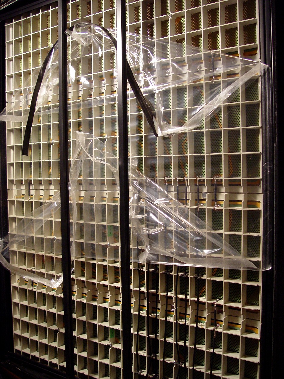
This image shows the dustcover of the ESL-63 partially removed. Completely remove the speaker's dustcovers and adhesive tape. Over time, dust accumulates on the dustcover due to the electrostatic charge on the panels. Take care when removing the dustcover to avoid depositing dust on the panels. Remove old Quad tape, clean off any guck, and vacuum.
|
|
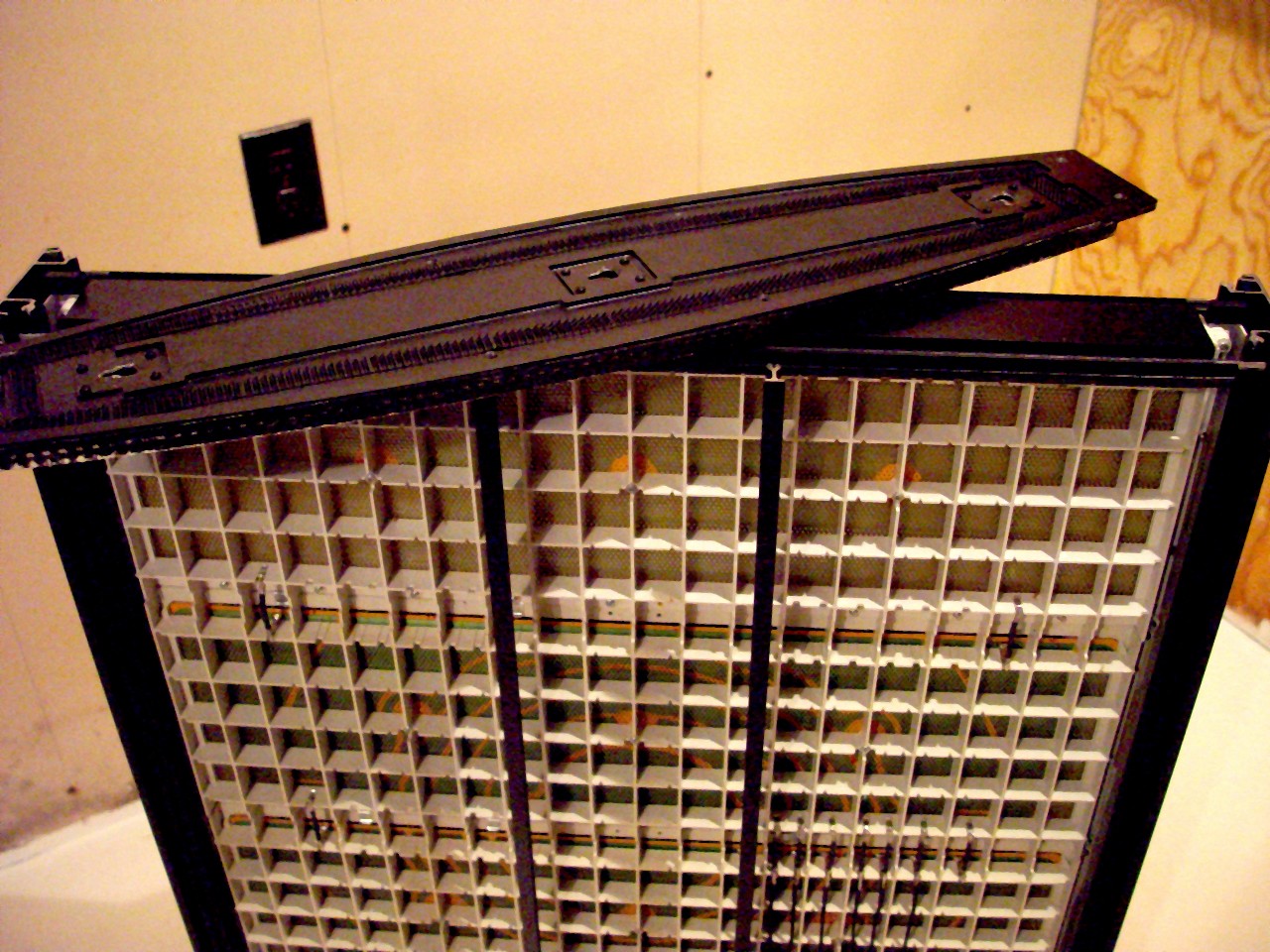
This image shows the top (horizontal) frame of the ESL-63. This is held in place by eight screws. Four screws (each 1/2" long) attach this to the side frame of the speaker, and another 4 screws (3/4" long) attach it to each of the four center reinforcing bars. Remove these eight screws, and the top panel then simply lifts off. Place the screws in storage boxes or in Zip-Loc bags, and label where they came from, to simplify re-assembly.
|
|
|
This image shows the horizontal metal extrusion on the top of the ESL-63. Remove it by pulling it upward. The horizontal and vertical extrusions are held together by pins which slide into slots. Pins fall out and get lost easily. Remove them and place them in a labelled storage box.
|
|
This image shows the two top segments of the ESL-63 after removal, exposing the panel assembly for removal.
|
|
|
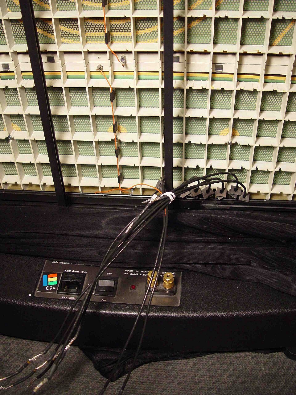
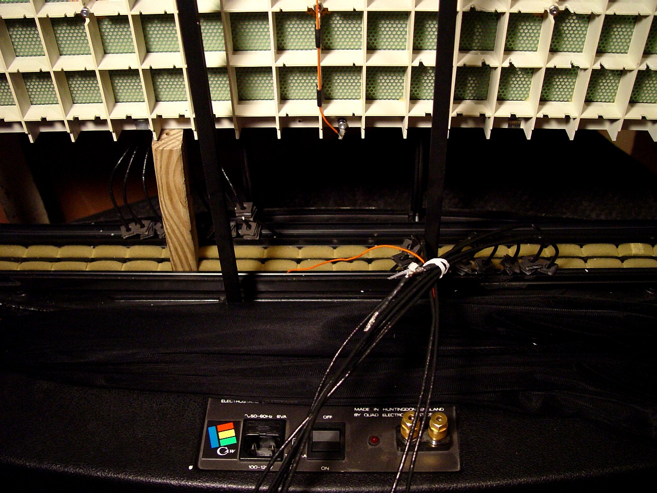
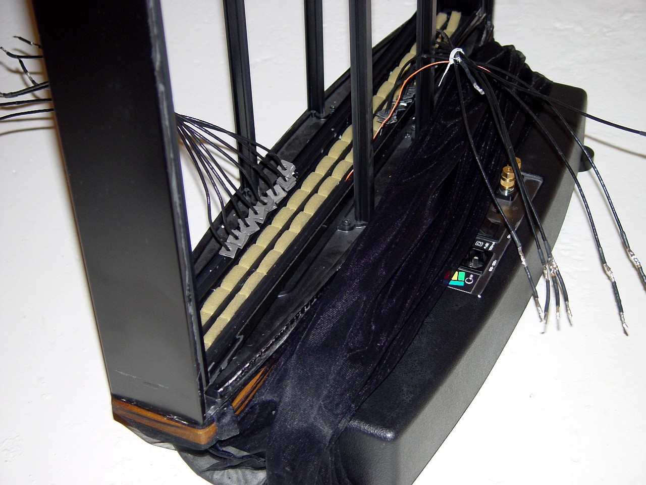
This image shows the amplifier output delay-line wires feeding the panels. These "Crosby Mod" wires are much thicker than those on a stock ESL-63, as a subsequent image shows. Disconnect these wires from the panels, so that the panel assembly can be removed. HIGH-VOLTAGE WARNING - NEVER touch any panel while either the high-tension supply or the amplifier is switched on. Take particular care to disconnect the amplifier. The ESL-63's plinth multiplies the voltage output of the amplifier one-hundred-fold, from about 50 volts to about 5,000 volts. Both the high-tension supply and the amplifier deliver about the same high-voltage charge to the panels. However, while the high-tension charge is limited to several micro-amperes, the amplifier can deliver several amperes. Quad speakers contain fatal currents and voltages. Consequently, take particular care to switch off and to disconnect the amplifier. Remove the steel spring clamps holding amplifier and high-tension (EHT) wires to the edge of the panel assembly. Place them in a labelled storage box. You can either unsolder or else cut all wires interconnecting the plinth to panel assembly. I prefer to cut them. It is quicker, and also less likely to cause damage, as unsoldering creates a risk of a solder-spit destroying a diaphragm. Cut each wire at the point of its first solder connection to a panel. The wires to cut are as follows : one EHT hot wire on the rear of the panel assembly, and 8 speaker wires on each of the front and rear of the panel assembly, 17 wires in all.
|
|
This image compares the wiring of a stock ESL-63 to that of the "Crosby Mod" ESL-63. In the foreground is the delay-line assembly and plinth-to-panel wiring from a stock ESL-63, and in the background is the "Crosby Mod."
|
|
|
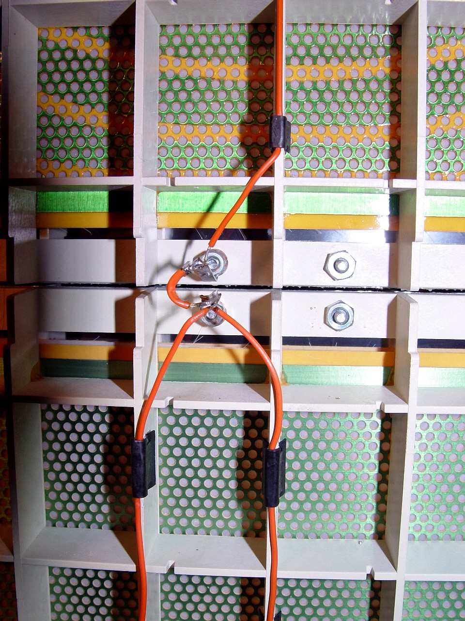
This image shows the EHT wire, which is red. From the plinth it runs up the rear centre of the panel assembly, and is soldered to the connector on the top of the bottom-most panel, which is where you cut it. Each of the four panels is connected to the EHT wire at both top and at bottom. Interconnect wires cross-connect the EHT wire of each panel to its neighbor. The EHT wire is in turn soldered to lugs on the panel-connection bolt. The head of this bolt contacts a conductive metal film strip on the interior of the rear stator panel, and this metal film strip in turn contacts the coated side of the mylar diaphragm, thereby transmitting the charge to the diaphragm. The mylar diaphragm is epoxied to the front stator panel with its coated side facing rear stator panel, where it comes into contact with the metal strip.
|
|
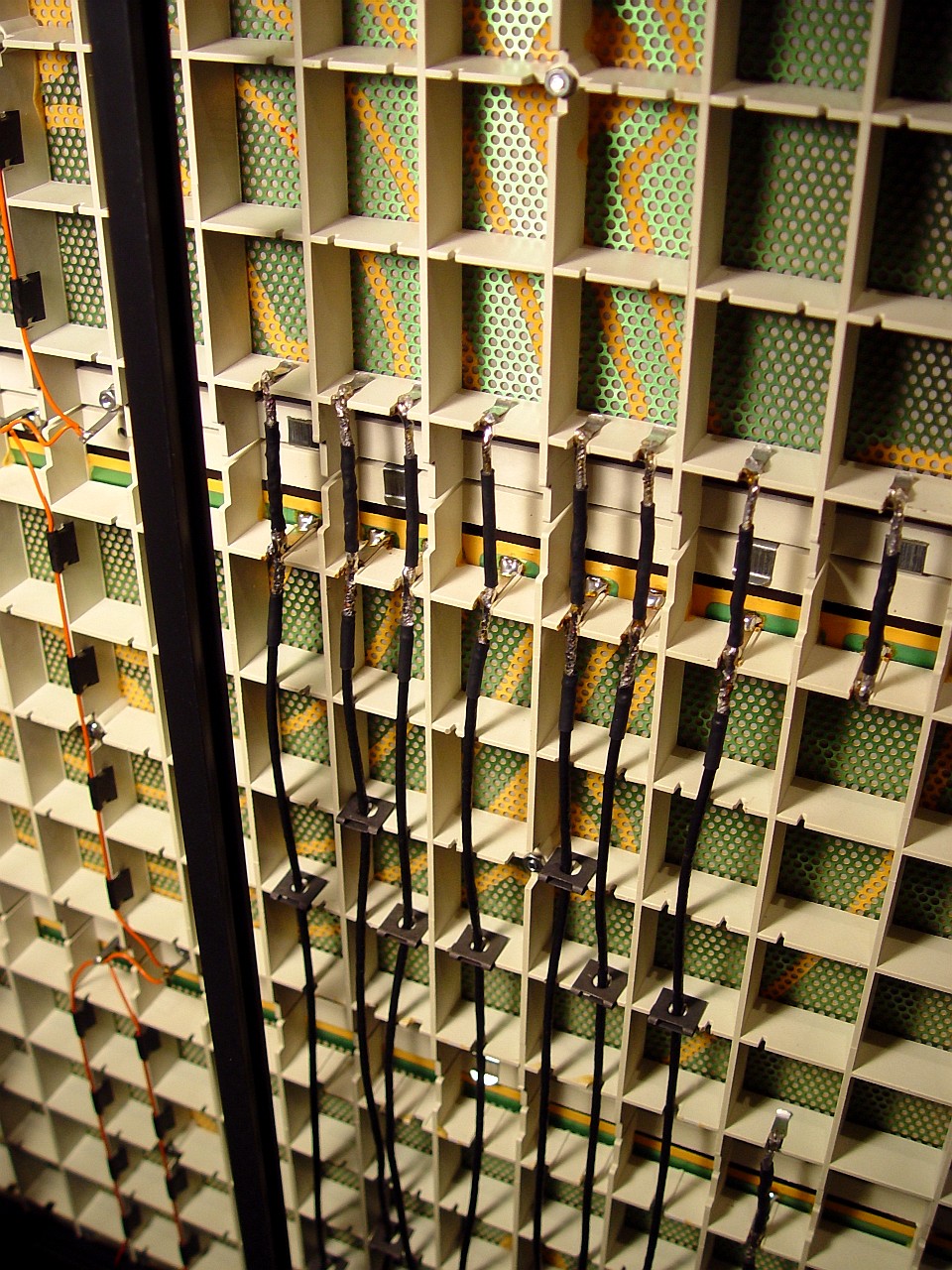
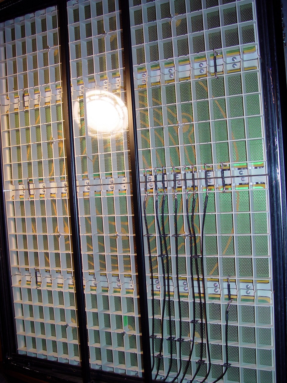
This image shows the speaker wires. On a stock ESL-63 they are very thin, and grey. Once you have removed the grills and dustcover, study the panel's concentric circles and the grey wires feeding from the plinth, and you will see that there is one grey wire for each one of the speaker's eight concentric circles. The leftmost grey wire corresponds to the centre circle. The next wire corresponds to the next concentric circle, and so on. Note that the wires and the circles are not aligned exactly - the wires are offset from the circles. Don't let this confuse you. Study the copper "tongues" on the stator panel to which each grey wire is soldered, and you will see that each one feeds back to its particular circle. The wires from the plinth attach sequentially to the panel assembly, and do not cross. Front and rear wiring is symmetrical. Note that the audio feed for the two outermost panels and for the outermost concentric circle of the two centre panels is the rightmost and the shortest of all the thin grey wires coming out of the plinth. Whereas all other grey wires attach to the panel assembly between the two centre panels, this one attaches between the bottom-most panel and its neighbour. Cut all speaker wires where they are first attached to the panel assembly. In addition to the speaker's delay line wires, there are also five "bridge wires" interconnecting the two outermost panels with the outermost segment of the two centre panels, which you will also have to cut.
|
|
|
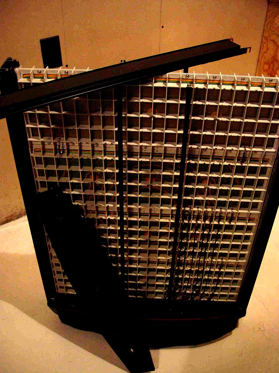
This image shows the entire panel assembly partially raised out of the speaker frame by a block of wood. Once the wires attaching the panel assembly to the plinth have been cut, the panel assembly can simply be lifted out of the speaker frame.
|
|
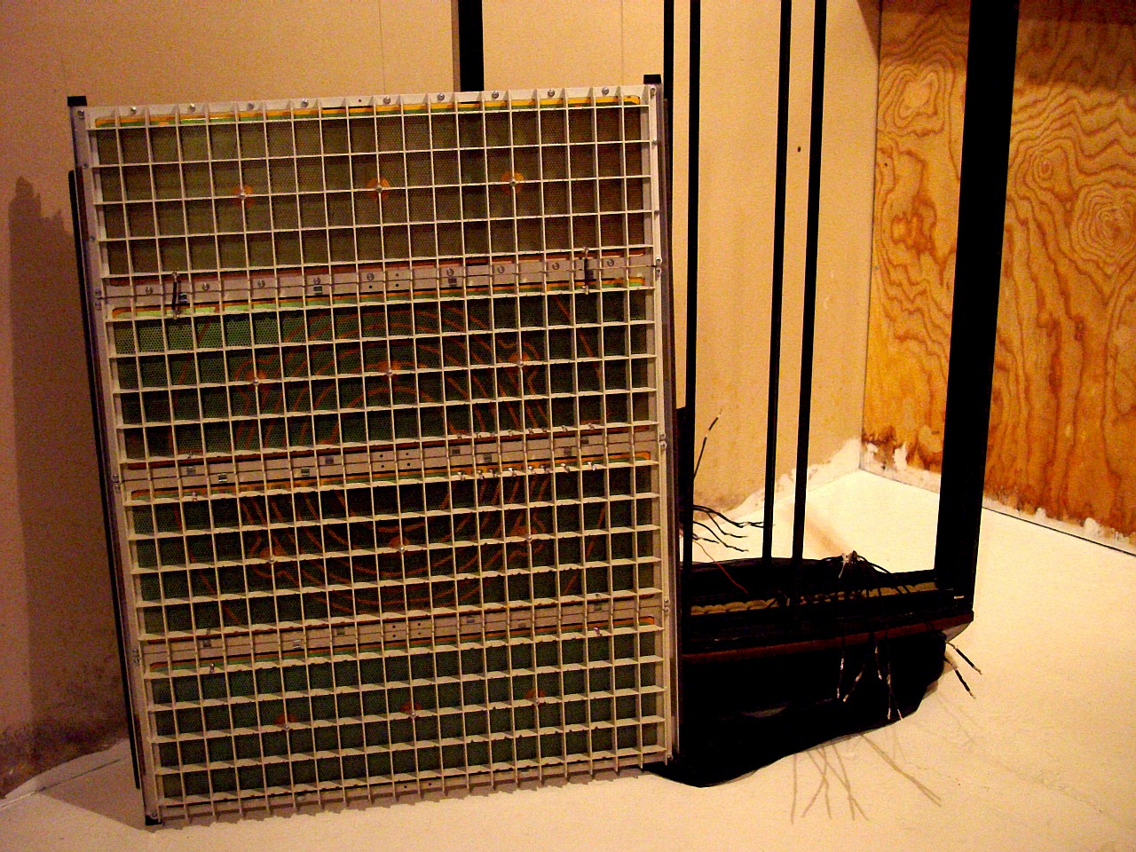
This image shows the entire panel assembly completely removed from the speaker frame.
|

|
|
This image shows the empty speaker frame after the panel assembly has been removed.
|
|
This image shows a single panel removed from the rest of the panel assembly. Note how thin and fragile the extruded metal panel assembly frame seems to be. Nonetheless, this frame is used without reinforcement in the "Crosby Mod" ESL-63 and also in the "USA Monitor." To remove the panel requiring repair, cut the wires interconnecting this panel to its neighbor and unscrew the four perimeter screws holding the panel to the extruded metal frame of the panel assembly. Remove them and place them in a labelled storage box. When replacing a panel after repair, ensure that it is installed correctly. The panel's interconect solder strips must be aligned with those of its neighbor, and the EHT connections must be on the rear of the panel assembly. Ensure that the rubber feet are on the panel assembly's extruded metal frame. Re-install the panel assembly in the speaker frame. The rubber feet on the panel assembly's extruded metal frame fit exactly into sockets in the base of the speaker frame.
|
|
|
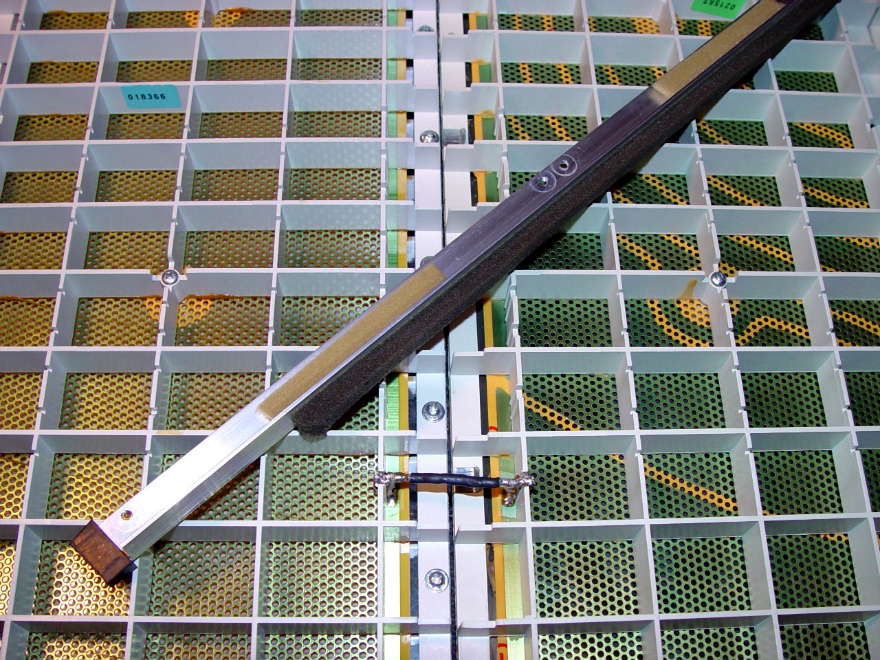
This image shows the extruded metal panel assembly frame laid on top of the panels. Note the liberal use of foam rubber.
|
|
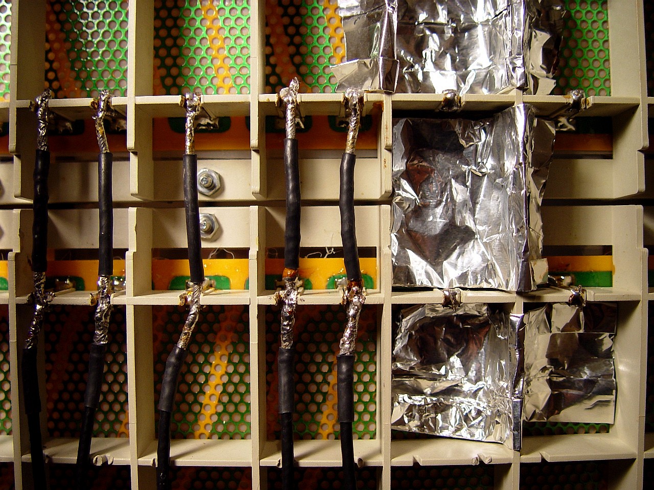
This image shows metal foil placed beneath solder connections so as to shield the stator panel and its diaphragm against solder splashes prior to re-soldering inter-panel connections. There are eight delay line wires and five panel interconnect wires on the front and on the rear of the panel assembly. Each of these wires has two solder connections, for a total of 52 solder connections. In addition, the EHT wire requires 7 solder connections, for a grand total of 59 solder connections. If there is a single solder-spit on any one of these solder jobs, you risk losing all your work. Shield every wire with metal foil as you re-solder it. Once all connections have been made and tested for contact, test to see if the speaker functions. If it does, proceed to final re-assembly. Replace the top extruded metal horizontal metal extrusion. Insert the 4 corner pins which hold the horizontal and vertical extrusions together, and push the extrusions together tightly.
|
|
This image shows the speaker with the panel assembly reinstalled and soldered, ready to have the dustcover film attached.
|

|

|
This image shows a package of window-seal kit, which you can buy at any hardware store. It contains film and double-sided tape to attach the film. It typically comes in 64 inch wide lengths, which yields two dustcover sheets. Cut dustcover-sized sheets from the film. Note the double-sided tape placed around the inner extrusion of the metal speaker frame, where Quad's tape originally was. The tape should go flush with the inside of the metal frame, so that the dustcover film cannot "drum" against the frame at high volumes. Before applying double-sided tape to the top of the speaker frame, push top and side metal extrusions tightly together - the tape and film actually help to hold the two extrusions together. Do not yet remove the backing cover from the tape.
|
|
This image shows the double-sided tape ready to have the dustcover film attached. The key to even dustcover tension without creases is to work from the panel centre to its corner-edge. Do not begin at the outside edge, and then proceed to the panel centre, as proceeding this way makes it difficult to avoid creases in the film. At the centre-point of each of the four sides of the speaker frame, cut a slit in the backing cover of the tape, as shown in the image. Peel about one inch of the tape back at the point of each slit, and fold it so that the tape cover can readily be grasped and peeled off. Feed the front dustcover film behind the speaker's two grill reinforcement uprights. Attach the film to the speaker frame at each of the four centre-points where the tape was peeled back. Detach and re-attach the film at these four points until it is under even tension. The film will now be tensioned at the four centre-panel locations in the form of a cross, and will be hanging loose in the four edge quadrants of the speaker. Go to any one of the four edge quadrants and peel off the tape backing cover in this quadrant. Stretch the film tightly along its diagonal, and attach it in the corner of its particular quadrant. Press the film onto the tape from the corner to the centre. The film is now attached to the double-sided tape uniformly over the entire quadrant. Repeat for each of the other three quadrants. Repeat the entire dustcover application process for the other side of the speaker. Once dustcovers have been installed on speaker front and rear, remove any remaining slack points with a hair dryer. Hold it about 4 inches away from the film. If the ESL-63 had them, replace the front and rear dustcover damper.
|
|
|
This image shows the speaker with the dustcover film attached. Now replace the top panel covers, in the reverse order of dis-assembly instructions. Note that the 4 @ 1/2"" screws attach to panel perimeter, while the 4 @ 3/4"" screws attach to centre reinforcing bars (one for each center upright). The speaker is now finished and re-assembled, except for grill replacement and for pulling the sock backup. Replace the speaker grill. Replace damping tape on side edges of grill. Align grill with notch in speaker base. Check that grill-to-earth spring clip at base of speaker is not bent or does not pass thru grill. Push grill into notched extrusion on one side of frame. Bend grill gently, and push into corresponding notch on other side of frame. Apply duct tape at top and bottom of grills. Pull up and re-attach cloth sock.
|
|
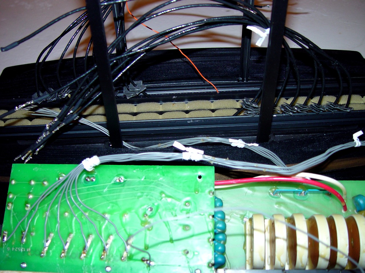
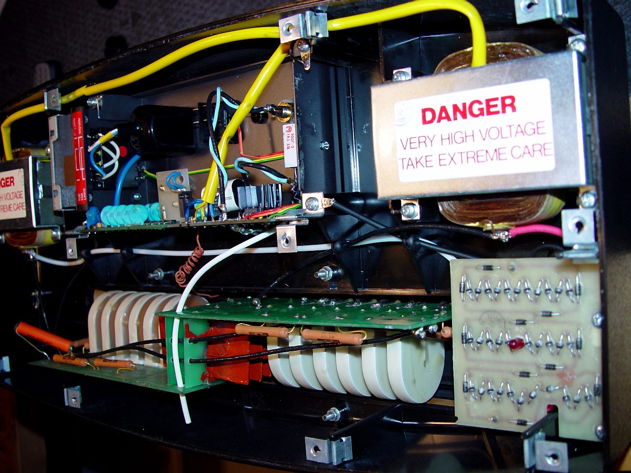
This image shows the electronics in the plinth of a "Crosby Mod" ESL-63.
|
|
|
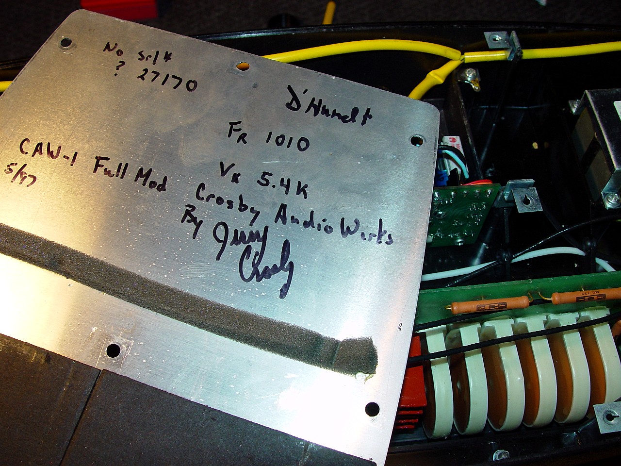
This image shows the "certificate" of modification, written on the inside of the baseplate of the plinth.
|
|
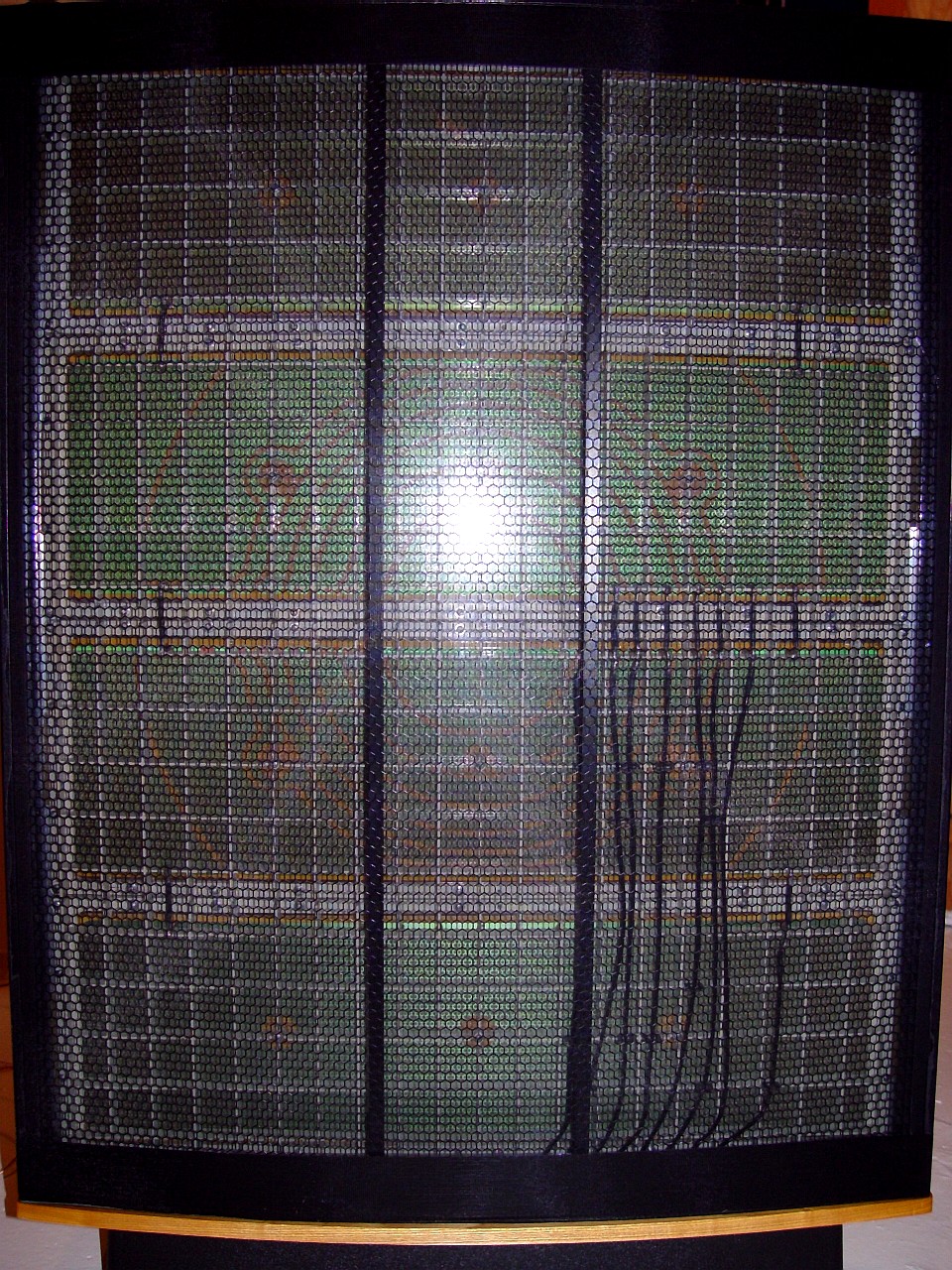
This image shows a very elegant Crosby ESL-63 with all four of its panels rebuilt. The beautiful open honeycomb grill and sheer nylon sock reveal the speaker interior.
|
|