click on any pic to download a ~2MB huge a hi-rez photo
|
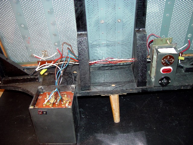
This image shows the ESL-57 from the rear with the grill removed, and with the output transformer also removed and placed upside down behind the speaker. This is so as to disconnect the treble panel's wires from the transformer.
|
|
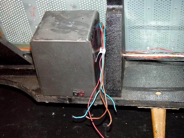
This image shows the ESL-57 from the rear with the grill removed, and with the treble panel's wires disconnected from the output transformer. Given that the output transformer is heavy, and the wires connecting it to the bass panels are fragile, the transformer has been bolted back in place while the treble panel is being repaired, to avoid accidental damage.
|
|
|
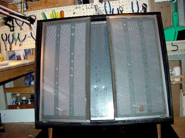
This image shows the ESL-57 from the front with the grill removed, and with the two brackets which hold the panels in place also removed. Removal of these locking brackets permits the two bass panels to be slid out of their bed in the frame, which in turn allows the treble panel to be removed.
|
|
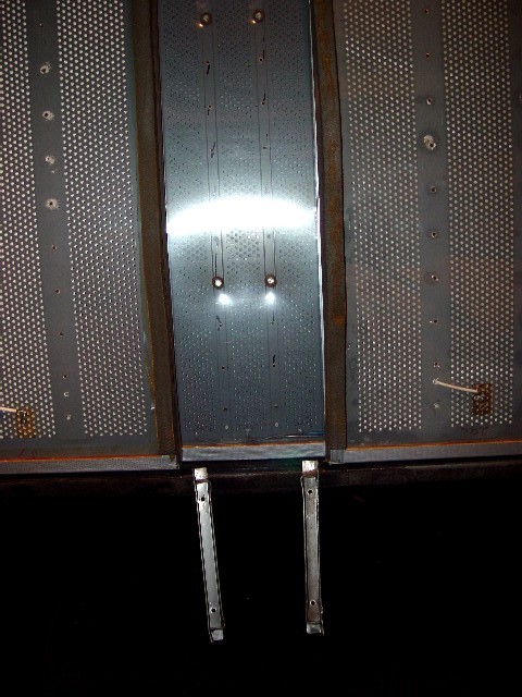
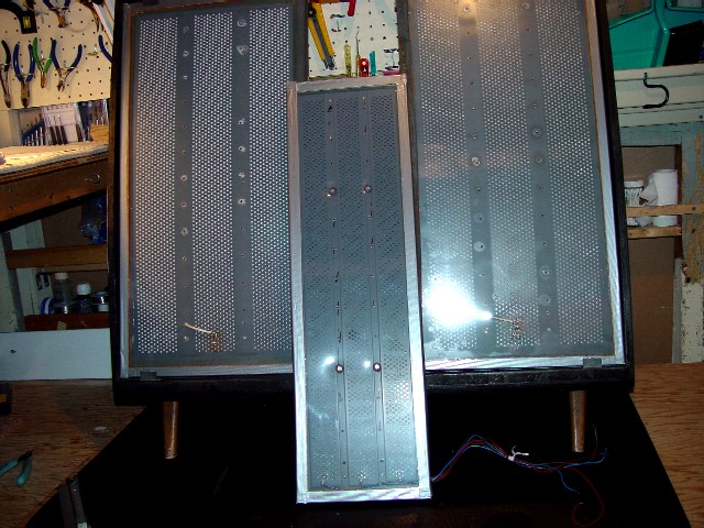
This image shows the ESL-57's bass panels slid partially out of their bed in the speaker's frame, sufficient to permit the removal of the treble panel.
|
|
|
This image shows the ESL-57 with the treble panel removed.
|
|
This image shows the treble panel with its dustcovers removed.
|

|
|
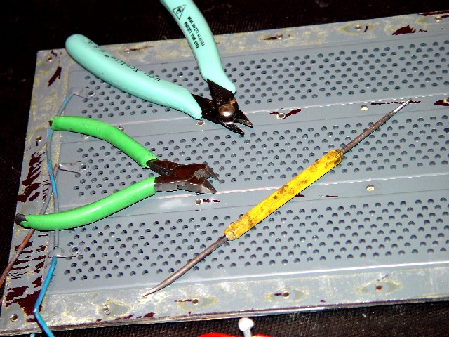
This image shows the tools I use to remove the rivets from the treble panel.
|
|
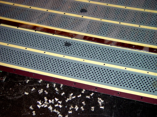
This image shows the treble panel's two stators opened. An arc burn is clearly visible on both stators. In the foreground are the panels' original rivets. The reddish colour on the perimeter of the stators is the natural colour of the plastic used in the stator. Quad covers this with a grey paint.
|
|
|
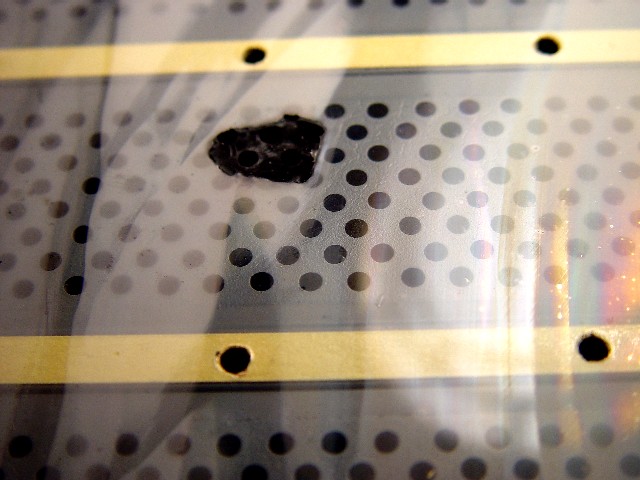
This image shows the arc burn on the diaphragm and on the interior of the rear stator, to which the diaphragm is bonded.
|
|
This image shows the diaphragm removed from the stator, and the hole burnt in the diaphragm and on the interior of the stator.
|
|

|
This image shows the stator panel clamped to a workbench, and the epoxy on the perimeter of the panel being scraped off with a wire brush. The straight-edge clamped over the stator prevents the wire brush from damaging the panel interior. Sorry about the image's blue tinge.
|
|
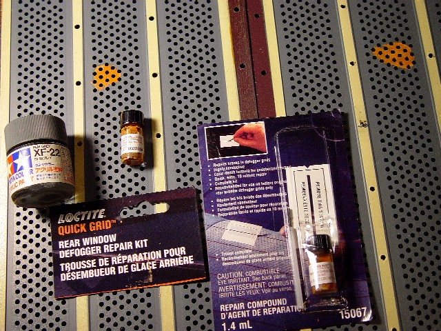
This image shows the materials I use to repair the arc burn on the treble panel. After cleaning the soot deposited by the arc burn with a toothbrush, I cover the burn area with electrically conductive paint. I use Loctite rear window de-fogger paint, which can be bought in any store selling automotive supplies. I then conceal this with Tamiya grey plastic modeller's paint, which can be bought in any hobby store.
|
|
|
This image shows the interior of the stator panel after it has been repaired. I cannot find a shade of grey that matches Quad's original colour exactly.
|
|
This image shows two thin strips of copper foil leading from the two holes where the EHT wire is connected to the two bolts which feed high-tension charge to the diaphragm. These strips improve the transfer of the charge to the diaphragm. A later image ( EHTfoil2.jpg ) shows the copper strips projecting on the outside of the panel, in direct contact with the EHT bolt. This self-adhesive copper foil can be bought at any store selling stained-glass supplies. The foil is so thin that it has a negligible impact on the stator-to-diaphragm gap. In fact, any Quad panel with a few loose rivets would probably have a greater gap.
|
|
|
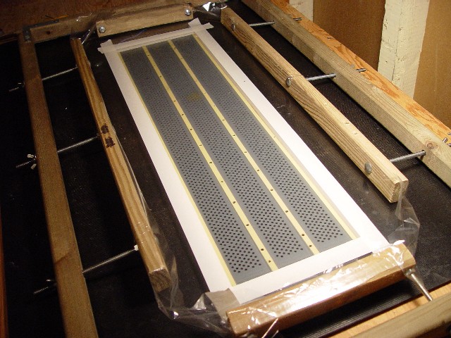
This image shows the tensioned diaphragm in the stretching jig laid over a stator panel, for the purpose of masking the diaphragm prior to coating.
|
|
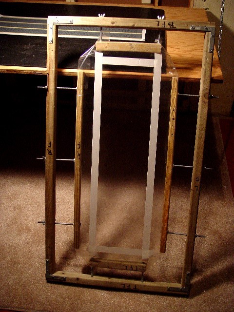
This image shows the masked and tensioned diaphragm prior to coating.
|
|
|
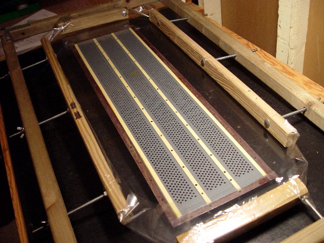
This image shows rear stator panel being bonded to the diaphragm.
|
|
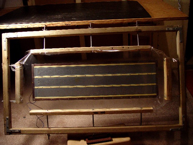
This image shows rear stator panel after it has been bonded to the diaphragm.
|
|
|
This image shows the diaphragm after it has been bonded to the stator panel, with bolt pass-through holes melted in it. When it is torn, Mylar tends to rip like candy-wrapper. Holes must be pierced in the diaphragm at each bolt-hole, so that the bolts do not rip the diaphragm when they are installed.
|
|
This is another image of the diaphragm with bolt pass-through holes in it.
|
|
|
This image shows a detail of the treble panel after it has been re-assembled. Notice the bolts which replace the original Quad rivets, and notice the continuation of the copper foil strip from the interior of the panel, to the panel exterior, where they are in contact with the EHT contact bolts. The wire from the EHT to these bolts is not visible because it connects to the rear of the panel.
|
|
This image shows the rebuilt treble panel with its dustcovers replaced.
|
|

|
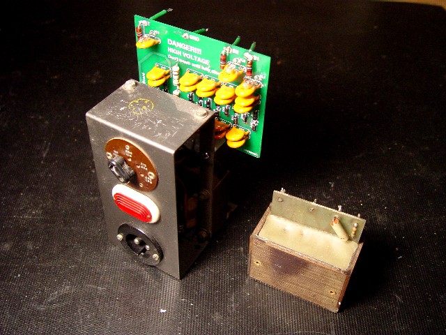
This image shows a Quad rectifier unit with its original EHT block, and the replacement Enquist EHT unit alongside it.
|
|
This image shows a Quad rectifier unit with a replacement Enquist EHT unit installed, and the original Quad EHT block alongside it.
|
|
|
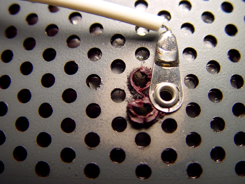
This image shows the lug to which the wire from the output transformer is attached. It shows that the lug did not attach well, and it took two attempts to get it to grip. Although I cannnot be certain, it seems that this defect occured when the panel was originally built by Quad, as the rivet could only have been clamped from the interior when the panel was open, and there are no signs that the panel was subsequently opened by one of its owners. I have seen several instances of the bass panel rivet pulling free of the stator panel. The cause seems to be softening of the stator panel's plastic under the heat of soldering speaker wires to the panel solder lug. The paler paint around the immediate area where the lug contacts the stator panel is the conductive paint which transmits the amplifier output over the entire stator panel. Elsewhere on the panel the conductive coating is concealed under the grey paint Quad used to cover the panel. Other images show that the natural colour of the plastic used in the stator panel is either deep red or white.
|
|
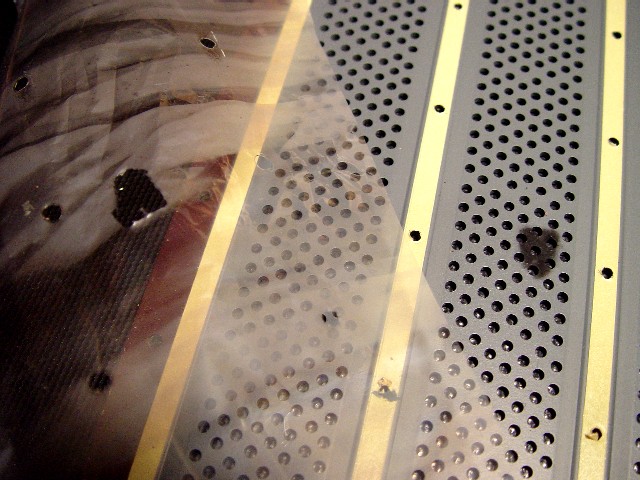
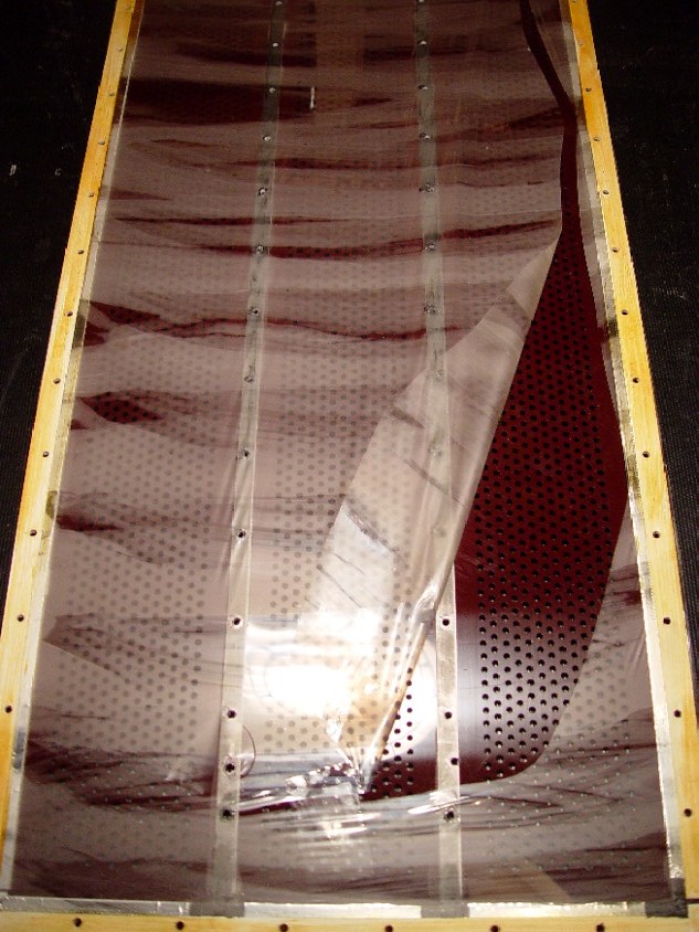
This image shows a torn bass panel diaphragm. Once a rip occurs, the film splits like candy wrapper. Unlike the treble panel diaphragm, which is made of mylar, the bass panel diaphragm uses a form of Saran. The reason is that Mylar is inelastic, and the bass panel diaphragm must be elastic so as to accommodate the diaphragm displacement needed to reproduce bass frequencies. This in turn probably forced the decision to have the conductive coating on the outside of the panel, so as to preclude arcing damage. By contrast, the ESL-57 treble panel has its conductive coating on the inside. This means that it is possible to drive the treble diaphragm into contact with the conductive coating, but not the bass panel. Consequently, unlike ESL-57 treble panels, ESL-57 bass panels are rarely damaged, and rarely need rebuild. On this image, and on the following "BassInterior.jpg" image, the streaks on the diaphragm indicate how haphazardly Quad's diaphragm coating as applied. It was painted on crudely and erratically with a brush, and as you can see, the thickness of the coating varies dramatically over the diaphragm. This may explain in part why it can take up to a day for a Quad panel to build up to a full charge.
|

|
|
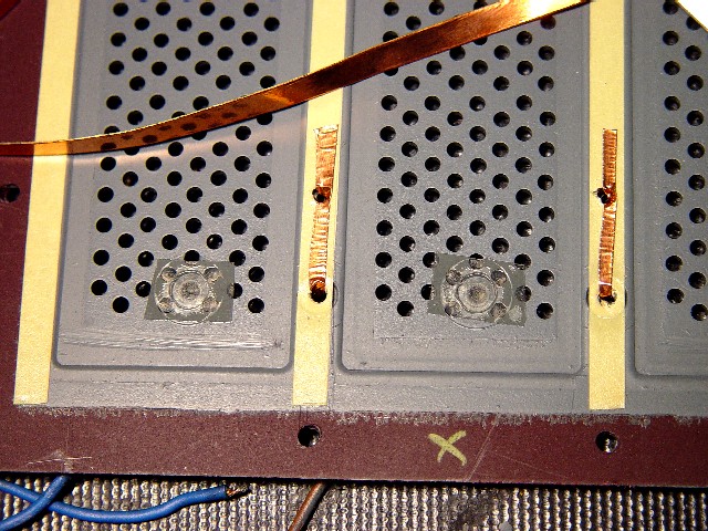
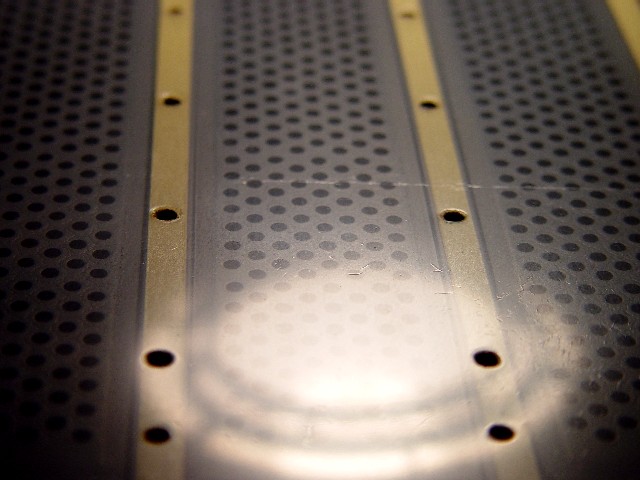
As with the previous "BassInterior.jpg" image, note the streaks on the diaphragm indicating how unevenly the diaphragm coating was applied. Note also that the metal rivet holding the solder lug passes through to the interior of the stator panel, where Quad covers it with an adhesive plastic film to prevent the diaphragm from coming into contact with the rivet and arcing. The conductive strips running around the panel perimeter and down the two centre spacer strips transfer the EHT charge to the diaphragm. The conductive coating on the exterior of the panel is applied only to (i.e., aligned with) the perforated area that you see on this interior view. Thus there is no overlap between the exterior conductive paint and interior conductive strips, but a considerable part of the radiating area of the diaphragm is not driven, and is passive. The undriven area is a width of about half an inch on either side of each conductive strip, corresponding to a total undriven panel width of about 3 inches. Given that the bass panel is only 13 inches wide in total, the undriven width comprises a significant part of the total width. On the ESL-63, the undriven width is negligible, comprising just half an inch around the panel perimeter.
|
|
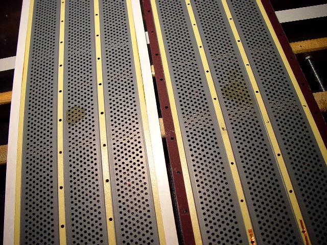
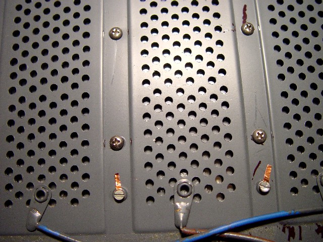
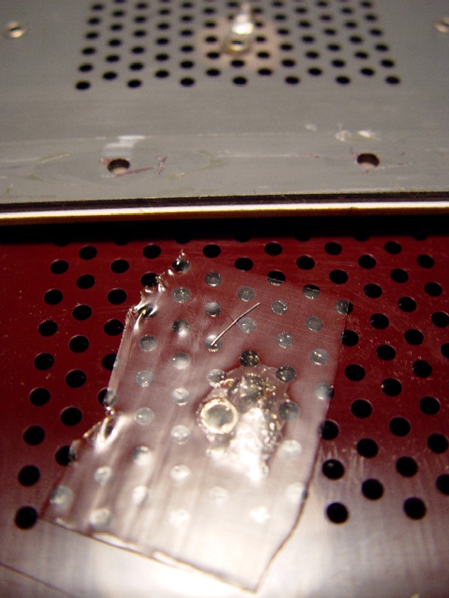
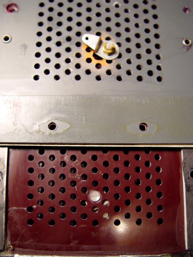
This image shows the way Quad attached the speaker wire to the bass panel, viewed from the inside (foreground panel) and outside (background panel). The lug is attached to the stator panel by means of a metal rivet. Elsewhere on the stator panel, the conductive coating is only on the outside of the panel, but at this specific point, the rivet conducts the charge to the inside of the panel. Arule of electrostatic design is that the stator-to-diaphragm gap must be constant over the entire stator panel. Quad violated this rule on the ESL-57 bass panel, and the stator-to-diaphragm gap is very small at this particular point and the panel is pre-disposed to arc there. Quad's solution was to cover an area of about 2 inches by 2 inches around this rivet with a thick plastic shield, to prevent arcing. This is not an ideal solution. What happens is that air is trapped at the point of greatest diaphragm displacement, and in addition the effective radiating area of the panel is reduced. There was obviously no audible difference, or else Quad would not have done it. Nonetheless, it's surprising to note that some of the steps Quad adopted when it originally manufactured the ESL-57 were quite crude. While it's easy to be critical with hindsight, the truth is that it was an incredible speaker then, and still is.
|
|
|
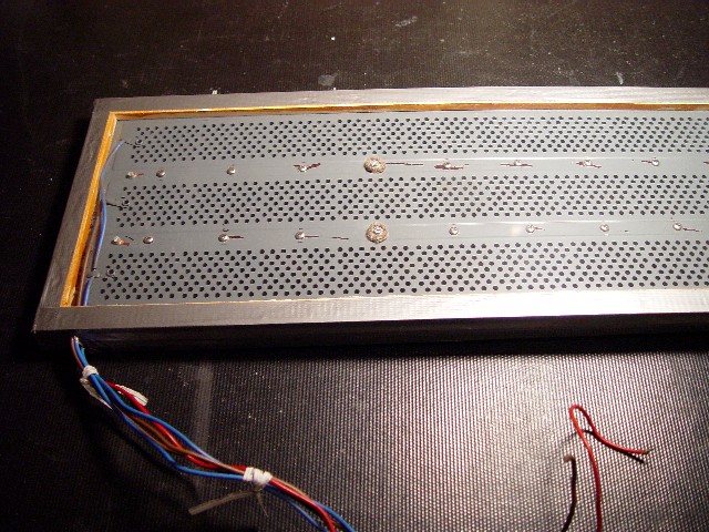
This image shows the way I attach the speaker wire to the bass panel, viewed from the inside (foreground panel) and outside (background panel). The lug is attached to the stator panel by means of a non-conductive nylon bolt. This means that the stator-to-diaphragm gap is constant, that there is no need to shield the bolt, and consequently none of the stator panels holes are blocked. In addition, there is no risk of the lug pulling free, as occasionally happens with the Quad rivet.
|
|
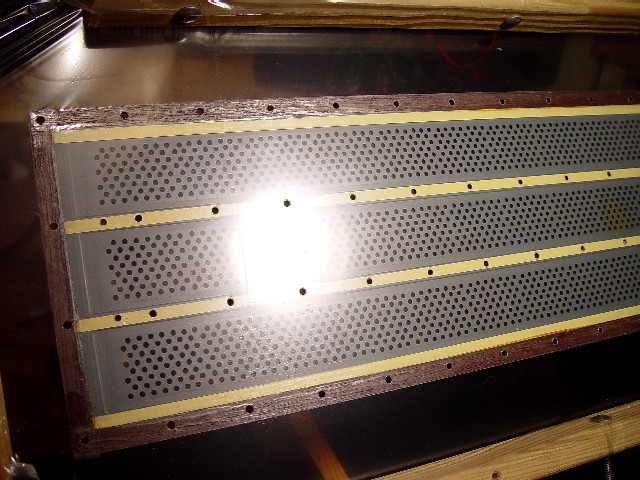
This image shows the rear of an ESL-57 bass panel after its wiring and dustcover have been replaced. I re-connect the panel's wires to the speaker with insulated set-screws. This is cleaner and simpler than soldering them, and it also makes it easier for the client to re-install his own panels after I have rebuilt them.
|

|

|
This image shows the rebuilt ESL-57 from the rear, prior to replacing damping mats and rear grill.
|
|
This image shows the rebuilt ESL-57 from the front, prior to replacing the front grill.
|

|