s.hum's Magneplanar 1.6 *Jensen* XO Upgrade
s.hum's Magneplanar 1.6 *Jensen* XO Upgrade
Preamble and Disclaimer
Much thanks to Mart and company; to Ed Hsu and Paco for their thorough *tweaks* guides upon which these mods are based; to MikeCh and Arbelos for their numerous posts and suggestions; and to all the forum members who preceded me on the 1.6 XO mods and replied to my numerous questions.
Lest it not be clear by now, *none* of the following material is original but is presented to illustrate the choices I made from all the groundwork laid out by the forum membership.
A special thanks to Hans Jensen of Jensen Capacitors for patiently answering all my unrelenting questions about the various cap and inductor choices to be made.
I hope that what follows will illustrate how easily this upgrade can be performed – if I can do it, anyone can J – and encourage others to do so. It is such a significant upgrade – more than a tweak – that I cannot say enough about it. I don’t know of any post indicating anything less than an outstanding improvement to the already remarkable 1.6.
I have only described the particulars of my XO build and some of the decisions (rationalizations) made along the way. Advance apologies for the verbosity. Wiring details and specifics should be obtained from the very detailed aforementioned guides above by Ed Hsu and Paco.
Choices
Internal or external XO? Probably like most, my first inclination was to build an internal XO and preserve the svelte dimensions of the planar form. But after determining that I wanted to go with a copper air core inductor and Jensen PIO caps, either of which necessitate an external XO, the choice was clear. Thus, this *all Jensen* XO came to be. I chose Jensen for both the inductors and caps because I was keen to sample their particular magic: their use of natural fibers (paper) in these hand wound components appealed to me, the science of which is beyond my comprehension.
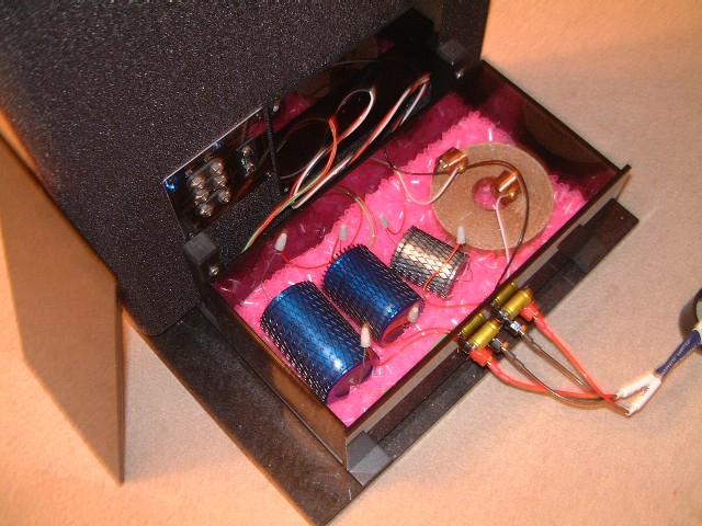
After working things out with Hans Jensen, I went with a custom wound 3.5mH 12awg copper air core inductor coupled with a 25mF metallized paper shunt cap for the midbass low-pass filter, and a 10mF + 12mF aluminum PIO caps combo for the QR tweeter high-pass filter, all matched pairs. Copper PIO caps I am certain would have been even nicer but at significantly more cost which would have brought other considerations into play, including upgrading to 3.6’s (if one ignored all the other attendant demands such as higher amplification)!
The only other XO parts that needed to be sourced were wiring and connectors. I selected some British made binding posts from PartsConnection which they use on their preamp kits – having lucked out on their sale of Cardas copper binding posts – and chose lengths of 15.5 and 17.5 gauge Cardas Litz hook-up wire. I picked up some of the hotly debated (on the forum) RadioShack screw down connectors but eventually decided to go with the much simpler marrettes since I was not using the flat Goertz speaker wire for my hook-up wiring.
External XO Box
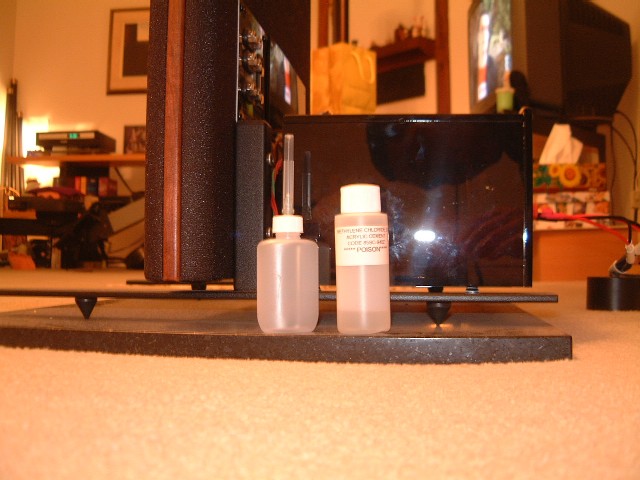
After searching for a ready made acrylic box I decided for the money that I would be better off making my own, yielding a two-fold benefit: custom dimensions and color. I designed a box that would be approximately 14w x 5h x 7d inches and ordered the pre-cut and polished smoked ¼ inch thick acrylic pieces from a local plastics supplier along with the methylene chloride (acrylic solvent). Two 8 x 5½ inch 1/8 thick smoked acrylic pieces (polished all four sides) were cut to cover the internal XO section of the 1.6’s where I would be running the wiring through.
Hint: Only have the exposed edges polished, else the edge joins with the solvent won’t be as sound. You can do this yourself with a flame – I didn’t feel like practicing since I was only making one set of boxes – or have the supplier do it for you.
Before assembling the boxes, drill all the necessary holes. On the front piece for the binding posts and the back piece for the exit wires (I chose to run my hook-ups directly to the speaker tabs as opposed to another set of posts and the additional connects). Entry wire holes and four small countersunk holes in the corners of the 8 x 5½ inch pieces were made to accept small screws to affix the plate to the 1.6 internal XO area.
I designed my box so the top piece simply rests on the top of the box. The front piece was made larger to provide a 1/8 inch extension around the box in similar fashion to the Audiomat Arpege looks (taking into account the resting top piece) which provides a nice side to line the top piece up against when placing.
Pre-assemble the box with a small pieces of masking tape, enough to tack things into place securely. You don’t need to run tape the length of the sides. Starting on the bottom – or whatever side is easiest to do so – run a *very* small bead of methylene chloride along *one* side in one smooth motion. Hold the side tight about a minute for the bond to set.
Warning: Methylene chloride is extremely toxic, very nasty stuff. Proper ventilation and care should be exercised. If you use the stuff regularly then you probably already have the full metal jacket to protect yourself. For a one time only project, I just tried not to splash myself too much with the stuff, washing my hands regularly!
Hint: Assemble the box on an inert smooth surface like glass – I used the polished granite tile my 1.6’s stand on. The solvent runs like water out of the applicator which has a hollow needle and seeps readily into the joined sides. It is literally a solvent and some of the dissolved acrylic will likely run onto the surface below. Don’t put paper under your box or you’ll have paper glued to the bottom of your box! The solvent evaporates quickly and the remaining acrylic traces can be easily scraped off the smooth inert surface with a knife. The bonding sets quite rapidly and only requires about a minute of applied pressure. You can adjust the pieces during the first minute or two, with the bond setting completely after a few hours.
Wires and Damping
While the box assembly sets you can prep the other items, notably your hook-up wires and damping material for the XO. Based on Ed’s findings, I avoided using a dense substance like sand and instead decided to line the bottom of the enclosure with cut pieces of plastic tubing – the (very unscientific) theory here to have maximum mechanical damping along with minimal dielectric effects. The material for this? Drinking straws from the local grocery store! By the time I finished cutting up the straws (about five packages!) into pieces, the boxes had pretty much set.
The teflon encased Litz wires were another story. You can see why they are so phenomenal: each of the very narrow ultra pure copper strands is not only spun in counter wound layers, but each darned strand is an individual conductor with a fine coat of enamel. Most use a tinning pot to burn off the enamel from the exposed ends but I found that this stiffened up the wire at the ends considerably – the heat affecting either the teflon casing or the copper itself or both. And since I was going to be using marrettes to join the XO components, I didn’t need my wires tinned. So I laboriously sanded off the enamel from the strands using very fine emery paper. (I did this over several evenings prior to the box assembly to rid myself of the most time consuming task!)
XO Assembly
When you get to this point, the rest is easy – and the most exciting and fun part. All the hard work which is more time consuming than difficult was, for me, cutting up the damn straws and prepping my Litz wires – honest! If you choose to use as others, packing peanuts and more conventional hook-up wire, you’re laughing. The box assembly took maybe an hour tops and that only because I was being anal and doing everything doubly carefully – thirty minutes is probably reasonable.
Insert your binding posts. Consult Ed Hsu’s guide for the wiring of the caps and inductors. I wired short lengths of wire from the binding post terminators to the caps and inductors. Marrettes secured the wires to the caps and I used a brass bolt, washer and nut compression to attach the wires to the flat copper inductor leads (punching a suitable hole in the copper first). Set aside the box.
The most cosmetic approach would be to remove the socks at least part way to gain access to the speaker tabs – or better yet, the speaker wires themselves for a wire to wire contact. But I was loath to remove the wooden siding, more from wimping out on the possibility that I would mess up their fit and finish. So I decided to cut the sock on the backside over the internal XO compartment.
Hint: Using a short straight piece of wood or a level, line that up along the outer edge of the internal XO enclosure as a guide for your staple gun to tack the sock down. These staples will be covered by the 8 x 5½ acrylic face plate.
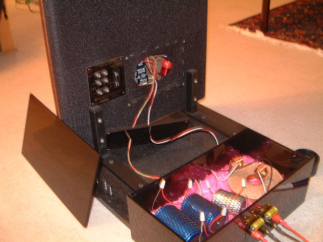
Cut a small slit in the middle of the internal XO enclosure area. The sock will peel back and you will see the internal XO. Following the leads up to the speaker tabs at the top of the enclosure you will see that they are easily accessible with needle nose pliers – small fingers can reach them easily. Note the colors and their polarity as in Ed Hsu’s guides, then remove the wires and tabs and tuck them away on the bottom of the internal XO enclosure (unless you want to remove the now to be redundant XO in which case you can clip the plastic ties and remove all the pieces – you will need to de-solder some wire connections in this case).
I hooked up my wiring such that the common points of the XO circuit met at the speaker tabs rather than at the adjoining component positions. Multiple wire lengths or fewer connection points? I chose more wires at this point – nothing was going to be permanent anyway at this stage – the thinner gauge runs for connecting to the caps, the thicker gauge for the grounds and inductor. Attach the female tabs to the wires and insert onto the male speaker tab connectors.
Hint: A little ProGold ensures a good contact as well as lubricates the tabs for insertion. Make sure your leads are marked for connecting to the XO components if they aren’t color coded.
Run the wires through the 8 x 5½ inch faceplate. Secure the plate onto the 1.6 and voila, that ghastly hole you just cut into your sock is neatly hidden. Run the wires into the back of the external XO box and finish up your hookup as per Ed Hsu’s wiring diagram.
Hint: I found marrettes very useful for this exercise. They are secure and quick to apply. The ones I used had copper inserts. Apply ProGold to the leads you are connecting and you are done. I tried the cap and inductor orientation as per Ed Hsu’s suggestion, as well as, reversed (which is the commonly practiced polarity orientation for caps and inductors: + to inner wind, - to outer wind) and ended up staying with the latter as per Hans Jensen’s suggestion – only because I couldn’t hear a difference. But with the marrettes in place, you can tinker with this and trust your ears.
VOILA. You are done. Give yourself a pat on the back. Double check the wiring. Then check again. Position the XO enclosure – mine sits on small vinyl cushions affixed to the top of the maggie feet. With your amp turned off, hook up your speaker cables. Turn the volume down on you amp and fire it up. Slowly inch up the volume and enjoy.
Post Mortem
Fuse: This is another hotly debated issue – in all my years of audio I have never blown a speaker let alone a speaker’s fuse. Before even this mod, I had already bypassed the fuse and found a more than subtle benefit. Bypassing the fuse also simplified my XO implementation considerably. You will have to decide your comfort level without a fuse in the XO.
Binding posts: I’ll be swapping in a set of Cardas pure copper posts soon.
Zobel experience: The external XO made it easy to experiment with Zobels (I eventually settled on Jensen PIO’s and Caddock Power Film resistors) but that’s another topic! (Photo shows Jensen .01mF bypass cap across binding posts).
My XO Impressions