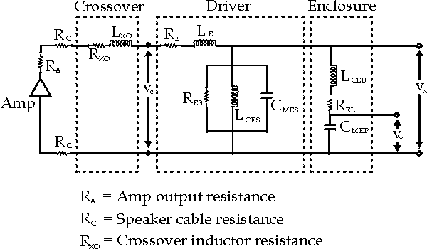
Here's an equivalent circuit for a raw dynamic driver. It doubles as one for a sealed (or enclosed driver) where “Rg” is speaker cable impedance & cross-over resistance & amplifier's output impedance. For what it's worth, most people ignore “Rms”.
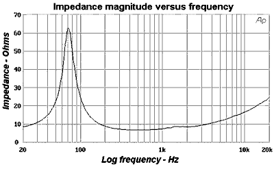
The magnitude of the impedance for real world driver is plotted below. The low frequency spike is modeled by the “Ces”; “Res”; “Les” section of the circuit while the high frequency slope is the responsibility of “Le” (voice coil inductance). 

From this we can glean Thiele-Small parameters, if not supplied. We will need the maximum impedance ( Zmax ≈ 63Ω ) atop the resonance spike & the minimum ( Zmin ≈ 7Ω ) in the well following. Now, we calculate the “R1” value which is the log mean value ( R1 = Sqrt[Zmax×Zmin] ≈ 21Ω ). Now we look for “f1” & “f2”, which are frequencies about the spike where the impedance is “R1” (IE: 48Hz & 105Hz respectively). In lieu of “Re”, we will ignore “Rms” & subsequently equate “Re” with “Zmin”, because Zmin = Re + Rms.Res = Zmax - Re Now that we modeled the difficult part, let's find “Le”. Let's take a read of 17Ω @ 10kHz where the inductance is significant.
( 56Ω )Ces = Sqrt[Zmax/Re]/( 2×p×(f2 - f1)×Res)
( 149.6 µF )Les = (f2 - f1)×Res×Sqrt[Re/Zmax]/( 2×p×f1×f2)
( 33.6 mH )Le = Sqrt[ Z10kHz² - Zmin² ] / ( 2 × p × 10000Hz ) Below is a reconstruction of the impedance curve in yellow.
( 0.247 mH )


Here's the actual published data for the same driver.
Re 6 Ω Le 0.24 mH Qes 0.34 Qms 4.27 fs 70.7 Hz
So when given this data:
Res = Re × Qms / Qes Here's the actual published values:
( 75.35Ω )Ces = Qes /( 2 × p × fs × Re )
( 127.56 µF )Les = Re /( 2 × p × fs × Qes)
( 39.73 mH )
Ces 125.0 µF Res 77.0 Ω Les 40.6 mH
Conjugate Filters
Now you know how to derive these values & you wonder why. Well, we can obliterate the spike by using a simple L;R;C conjugate filter. This is a series configuration whose entirety is wired in parallel across a dynamic driver's terminals. Therefore, the low frequencies look like a resistor as depicted by the red line in the above impedance graph.
0—————[ Ln ]—————[ Rn ]—————[ Cn ]—————0
Ln = Ces × Re² Rn = Re ×( Re + Res )/ Res
Cn = Les / Re²
Zobel Circuit
Similarly, a Zobel circuit nullifies the voice coil inductance. This R;C circuit is also wired across the driver's terminals. A graphed blue line illustrates what a Zobel does.
0———————[ Rz ]————————[ Cz ]———————0
Rz = Re + Rms So what was this about? Well, if you want a cross-over to work, it depends on your driver resembling a resistor.Cz = Le/Rz²
Acoustic Response
Is that the only reason? No. Acoustics response is proportional to the voltage drop across “Rms”.
In this case, we have the published measured data:

What happens if all you have the is the impedance graph instead? Well, a well known low frequency response curve is based on “Qh” & “fh” which is equivalent to “Qtc” & “fb” (the enclosed version of Qts & fs), respectively.fs = Sqrt[ f1 × f2 ] Here's the actual published values:
( 71 Hz )R0 = Zmax / Zmin
( 9 )Qms = fs × Sqrt[R0] /( f2 - f1 )
( 3.74 )Qes = Qms /( R0 - 1 )
( 0.467 )Qts = Qms × Qes /( Qes + Qms )
( 0.415 )
fs 70.7 Hz Qms 4.27 Qes 0.34 Qts 0.32 SPL 90.9 dB/m/W For those that understand complex equations ... the transfer fuction is :
(f/fh)² / { (f/fh)² - Sqrt[-1]×f/(fh×Qh) - 1 }

Associated group delay plotted in equivalent phase angle:

The equivalent electric circuit for a ported enclosure schematic is:

further elaboration