Letís start with the basics. If you have ever experienced static shock, you had a direct-current (DC) electro-magnetic force (EMF), or voltage measured in volts (V) cause the static charge (measured in coulombs). If the potential were sustained, so would the flow of electrons. This rate of flow or DC current is measured in amperes (amps). If you were a better conductor, the current would increase. This is called Ohmís Law.
V = I◊R Voltage is the product of current & resistance, where resistance is measured in ohms (W). So, the greater the resistance is, the smaller the current. That is precisely how resistors work as we massage Ohmís law to illustrate.
I = V/R Now suppose we have two resistors in series (R1 & R2). The voltage source would see a resistance equal to their sum. However, each resistor would only see a fraction of the source voltage (but share the exact same current). This is why itís called a voltage divider. So, through some algebraic manipulation Ohmís law looks like
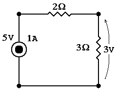
V1 = V◊R1/(R1+R2)
V2 = V◊R2/(R1+R2)
Now letís discuss parallel resistors. Ideally, they act independently to share the exact same voltage. Thus, each one draws its own additional current. Thus, the effective resistance seen by the source is the reciprocal of the sum of the reciprocals:
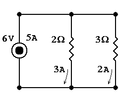
R = 1/( 1/R1 + 1/R2 )
Thus, if the 2 resistors are the same value, the effective resistance is halved not unlike dual exhaust system on a car. Also if one is much greater than the other, current seeks the path of least resistance & the effective resistance is just slightly less than the smaller one. Electronic testing equipment works this way. Their enormous resistance makes their intrusion imperceptible to the circuit.OK, so say you have a circuit whose impedance needs to remain constant but you want to reduce its output. This device is called an L-pad. We put a resistor in series (Rs) with parallel (Rp) with the original resistor (R). The Rp reduces the effective group resistance so that the additional Rs will have an effective resistance equal to the original R value.
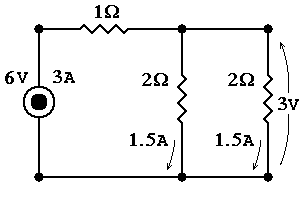
R = RS + 1/( 1/R + 1/RP )
At this point Iíd like to introduce decibels (dBs) because many use an L-Pad to uniformly reduce a driverís output without changing its crossover (XO) that is dependent upon the speakerís nominal impedance. So, if you had a 2W speaker in the above example, youíll end up with half the sourceís voltage across the speaker. Likewise, if you had an 8W speaker, Rp=8W & Rs=4W, youíd still half the voltage source.Now how does that translate into sound pressure level (SPL)? SPLs are measured logarithmically in deciBells (dB) named after the work Alexander Graham Bell (the telephone inventor) did on human hearing & deafness, who noticed that humans perceive sound 10 times as powerful as twice as loud & used it to measure signal loss in phone lines. The equation is ...
... where P is power defined as V◊I. Through more algebra we get ...
... or -6dBs. 6dBs know it. Remember it. It is a common value in circuits & now you know what it means. But, you say you want to cut a 4W speaker by -1dB hear are the equations.
RP = R ◊( R - RS )/ RS
You shouldíve got Rs=0.435W & Rp=32.8W.So, where does almost all of that power go? Itís usually said that itís dissipated, but itís done so by being converted into heat flux energy. Thatís why even solid-state amplifiers (that donít have heaters) can get hot. Often, theyíre called I≤◊R losses. This must be accounted for in circuitry. Certainly, one can easily see the sensitivity of current, since heat quadruples as current doubles. This is why voltage-source amplifiers overheat & why some have fuses that blow at a couple amperes to prevent it. This protects the amplifier from burning-up due to accidental short circuits like if the speaker cables touch, drastically reducing impedance load, causing a corresponding current spike, generating enormous amounts of heat.
However, we are dealing with audio signals which are alternating-current (AC). Ideal resistors react just the same regardless of the amplitude or frequency (cycles per second measured in hertz). This is not the same with all components.
AC Circuits
Capacitors (caps or ďCĒ measured in farads) for example are devices that accumulate current into static charges much like the aforementioned static discharge. In fact, some industrial caps can discharge a mortal charge. They work up until their breakdown voltage or rated voltage is exceeded. They basically are parallel plates separated by an isolator. When, a charge collects on one plate, it attracts an opposing on the other plate. This absorption of charge from the downstream line creates an absence of that opposing charge or a specter of the original signal, but all this accumulation (integration) of current takes time. Thus, the capís reaction isnít operating synchronous (in phase) with the signal. This discrepancy means resistance is no longer applicable for its operation. Here in the AC realm we speak of ohms in terms of impedance (Z) instead. Also, the amplitude is a function of frequency. This can easily see demonstrated by imagining a 0Hz (DC) signal which sees a cap as a broken wire (open-circuit). The same cap that conducts in AC doesnít in DC. An ideal cap varies linearly with the reciprocal of frequency (measured in seconds per cycle or period). This is why high-pass filters use a single capacitor in line (series) with the tweeter. The bass low-frequencies (long-periods, long-wavelengths) LFs are impeded more than treble high-frequencies (short-periods, short-wavelengths) HFs.
FWIW, we can use the same equations for parallel & series resistances, but substitute Zc for R. Hereís where we discover a seeming contradiction. You see the equations for equivalent capacitance look reversed. However, thatís because capacitance is inversely proportional to its impedance. The effective capacitance for series caps look like... (note: donít ever do this without huge bypass resistors to drain the enclosed DC voltage)
OTOH, parallel caps are used all the time. They reduce the less than ideal series resistance in real world caps while accumulating capacitance. Why you ask? Itís called a RC time constant.
This is why small caps are faster than large ones. Another similar concept using this phenomena is a bypass capacitor. You put a huge cap in parallel with a tiny one. You effectively couple the large capacitance with the smaller resistance. However, the different time constants in the signal path spark a controversy among audiophiles, but remains commonplace none the less.So, what precisely is this phase (measured in degrees) that everyone speaks about? Itís a measure of asynchronism that sinuous signals under go. Here we have a simple circuit to determine what is happening. The following parallel circuit can be used to determine these components independently.
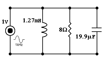
The following shows the voltage supplied to each vs. resultant current of each.
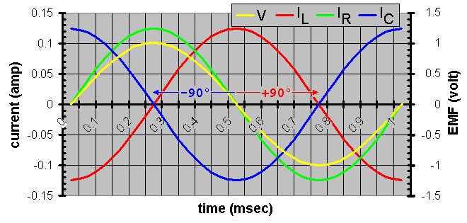
What would happen if we change the frequency? Well, the phase is identical but the amplitude changes. Why? Because, as I already indicated these new devices change impedance with frequency. The larger the impedance is, the less current is allowed. Hereís a plot of the frequency dependent impedanceís magnitude.
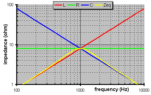
Take note of the equivalent impedance (Zeq) of the combined circuit. This is the load that the source would see.
1st order crossover
So, letís look at a simple crossover (XO) at 1kHz between 2 ideal 8W loads. Below is the high-pass filter portion. It is called a 1st-order because thatís the highest order of the polynomial in the transfer function (equation in the complex plane predicting behavior). However, most layman prefer to count caps & coils used. This has only one. Thus, 1st-order. It is serendipitous & convenient. However, in complicated circuits it is incorrect, but we can tackle that later. Here we must determine the value of the cap required. The proper value has an impedance magnitude equal to the resistor.
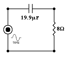
C = 1/(2◊p◊f◊R)
So, how does it work? Well, the too short of an answer is like a voltage divider the cap allows greater voltage to reach the load at HFs because its impedance is much smaller than the resistorís. Also, vice versa, at LFs the load sees very little voltage because the capís impedance is comparatively much larger than the load. How fast does it cut-off? It changes 6dB between the octave from 1kHz to 2kHz. That is an octave being a span between harmonics (factor of 2).
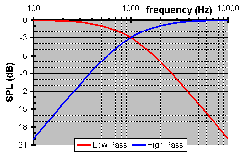
Why did I say ďtoo short of an answerĒ? It excluded phase. What is the phase? Well, phase here is dictated by the conglomerate impedance. While each component is a constant, each weights its own value by its own magnitude. Thus, the outputís phase is frequency dependent. Although, please notice as each circuit does less filtering, the phase zeros.
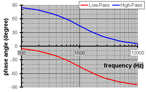
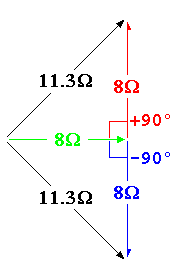
How does one obtain the value at each point? Well, each value is obtained through vector addition. It is a simple way to do the same trigonometry as the more obscure arithmetic on phased sinuous waves. Below we calculate the total equivalent impedance @ 1kHz. Since output is the resistance with no phase divided by the this component with positive phase. The output voltageís phase is negative.
Inductors (coils or ďLĒ measured in henries) convert the change (differential) in current into a magnetic field & vice versa which makes itís sensitive to acquiring nearby fluctuating magnetic fields called mutual inductance. (This also explains why some have ferrous cores as iron is a superior conductor for magnetic fields. This means less loops of wire comprising a coil would be required to induce a magnetic field. So, less wire translates into less resistance in the inductor. However, itís innate nature of staying magnetized creates distortion called hysteresis.) A coil is the natural antithesis of a capacitor. It is a short under DC operation. Thus, ideally, its impedance varies linearly with frequency. Also, the coil phases the signal in the opposite direction. Now you can understand why a series coil is used on a woofer. It impedes high-frequencies (HFs) where the woofer cone breaks-up (vibrates uncontrollably).
This 1st-order low-pass filter also requires its reactive component (namely the coilís impedance) to equal the magnitude of the resistor.
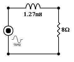
L = R/(2◊p◊f)
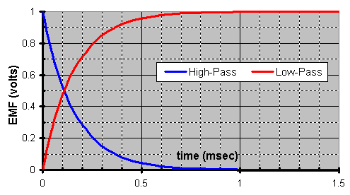
What happens when they add together? Well, you get a synchronous output with the input as you add (blend) equal contributions of -3dB @ Ī45į. FYI, the fact it doesnít phase means it can ideally reproduce a square wave as one can easily see by adding the 2 transients components shown below.
2nd order crossover
The easiest introduction to 2nd-order XOs right now is a band-pass filter. It is comprised of a LF 1st-order high-pass filter & A HF 1st-order low-pass filter, as such itís the only 6dB/octace 2nd-order filter. It passes everything inside that band.
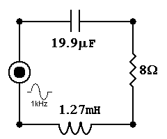
Hereís an introduction into the fact that more complex rules determine things here. Why you ask? Well, we just put a 1kHz high-pass together with a 1kHz low-pass. Did you expect this?
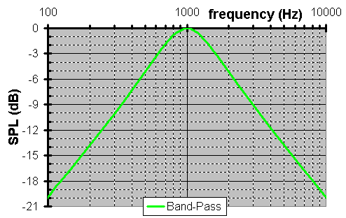
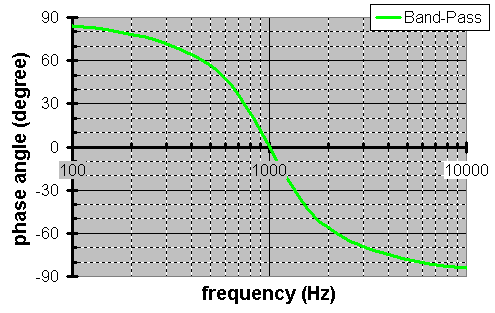
We combined 2 filters each of which was cut -3dB @ 1kHz & got one that wasnít cut at all @ 1kHz. That happens because of something called reactive power. Thatís when caps & coils store real power only to assist when needed. This comes with a control penalty which can range from inaudible to ringing. It all depends on personal tastes, perception, system, & Q. No, not the character from ST:TNG TV series. Q is a measurement of this frequency response behavior & also has lingering transient repercussions. Qís should be above critical damping of ½ lest it sound slow & less than unity lest it sound resonant. Common Qís are ...
| Q | |
|---|---|
| Linkwitz-Riley | 1/2 |
| Bessel | Sqrt[1/3] |
| Butterworth | Sqrt[1/2] |
| Chebychev | 1 |
In a bandpass, it is defined as ...
Plus, regardless of components used, 0dB cut will occur at midband defined as ...
The bandwidth is defined between these -3dB cut frequencies ...
f32 = ( Sqrt[4◊L/C + R≤] + R )/( 4◊p◊L )
So, you say that you have a load & want the values to make a bandpass between f1 & f2
C = ( f2 - f1 )/(R◊2◊p◊f2◊f1 ))
... with a Q of ...
Now, how many octaves does this band cover?
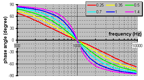
What does a family of 1kHz bandpass filters look like?
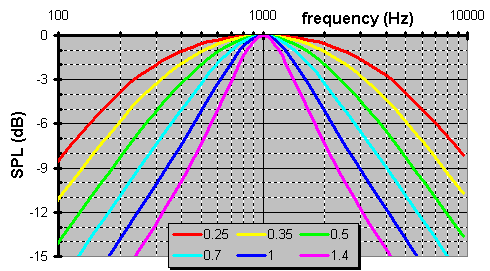
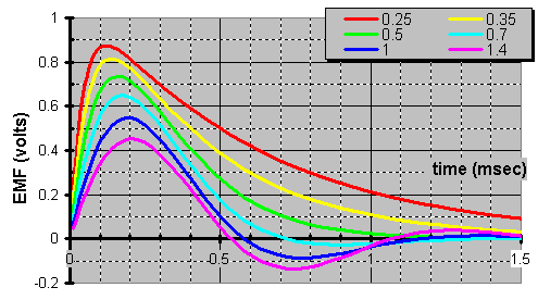
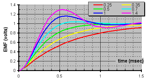
OTOH, hereís a real eye opener. See how the larger bandpass bandwidth contributes more in the step function yet never reaches unity due to the overdamping as shown below.
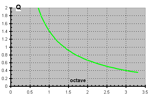
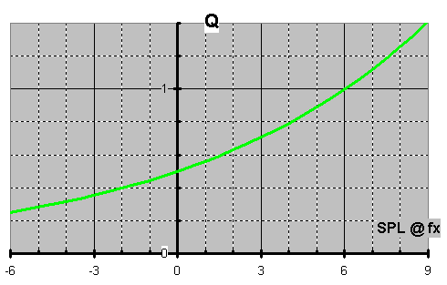
Hereís the relationship between Q versus bandwidth measured in octaves
Now, letís make a 2nd-order high-pass filter. We know that a series cap worked in a 1st-order XO. If we strap a coil in parallel to the output resistive load, we know it will reduce itís equivalent impedance especially as the frequencies lower. Thus, the impedance ratio will increase to greater effect. Thatís responsible for doubling the cut-off ratio to 12dB/octave.
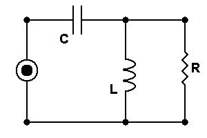
IOW, during LFs where the capacitor impedance is comparatively large with respect to the output resistance while the inductor impedance is comparatively small, therefore the output resistorís voltage is dictated by the current draw through its shunt inductor.
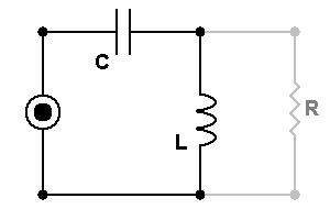
Furthermore, during HFs, the inductor seems huge & the capacitor seems small, which makes the high-pass filter virtually invisible.
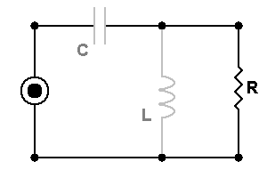
Do you want a certain Q? This depicts the sharpness of the knee in the response graph among other things as stated above. And, like the above bandpass filter, the high the Q the more abrupt the transition.
C = Q /( 2◊p◊fX◊R )
How about calculating the fx & Q of a given circuit ...
Q = R ◊ Sqrt[C/L]
Hereís what a family of curves of different Q resemble.
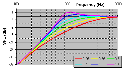
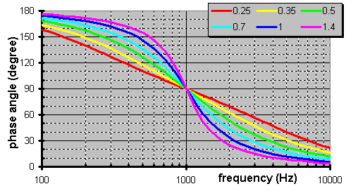
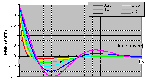
You can guess as well as I that a 2nd-order low-pass filter looks like ...
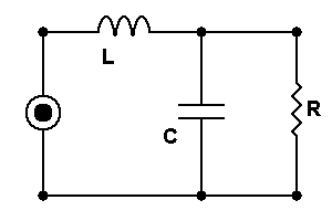
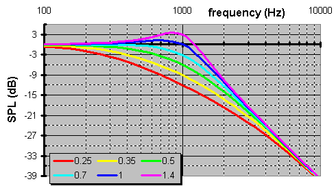
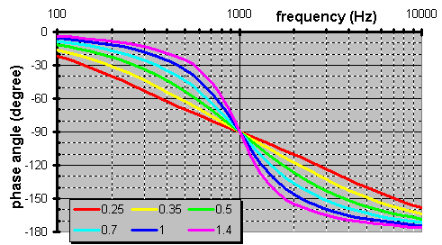
... but you what isnít obvious is the same L & C equations are applicable here.Hereís where phase begins to be important. Suppose we wanted a 2nd-order 2-way XO. Letís compare the phase of the high-pass versus the low-pass filters at the XO.


Not only are they 180į (out-of-phase) apart at the XO point, if the two filters have the same Q they always are 180į apart. So what, you say? If you recall the above definition of phase, that means one signal is the complete opposite synchronization of the other. Thus, at the XO frequency where signalís amplitude is split equally, the 2 are equal & opposite. Thus, we have complete cancellation (destructive interference). This is also known as a null, or no combined output signal.Is all lost? No. If we simply invert any one of the two they are in complete synchronization with each other. So, if you want the phase to sweep like the high-pass filter, invert the wooferís polarity (& vice versa). Perhaps you have heard of a phase aligned XO. Does it matter which Q we use? Letís see ...
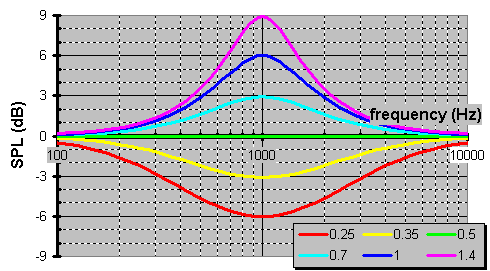
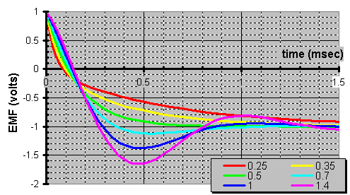
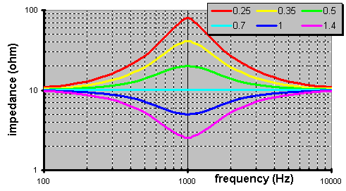
Hereís the accompanying family of impedance curves for which an arbitrary R=10W value is used to make these curves more visible on the log-log plot. Take note that the impedance doubles @ the XO for the LR, while its output is ruler flat.
So, why would anyone prefer a 2nd-order Linkwitz-Riley (LR) XO over a 1st-order Butterworth? Why deal with all those phase problems just to be unable to reproduce a step function when youíre done? Letís compare ...
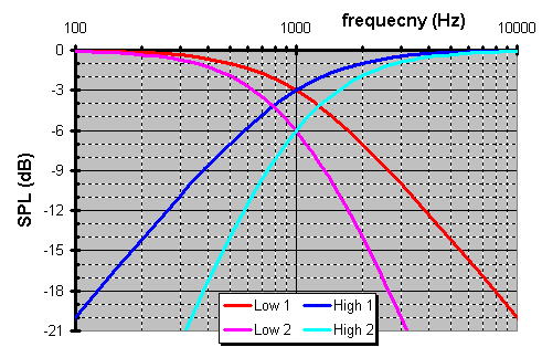
Both of these 2-way XOs have a pancake flat response. Yet, because the output from LR is synchronous, it affords you 3dB more isolation between the treble & midbass. On speakers this means you can purchase a tweeter that extends higher & a woofer that extends lower, because each driver is so isolated from the otherís operation. Also, a 12dB/octave (2nd-order) high-pass filter is a natural excursion limiting circuit. You see LFs require more volumetric displacement than HFs at the same loudness. Given a fixed diaphragm piston area on a driver, that translates into more excursion. So, this protects tweeters from the damage as it attempts to reproduce LFs.
3rd order Butterworth crossover
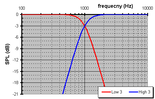
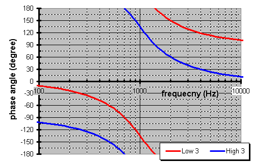
This is a flexible XO. It can sweep an entire 360į of phase as it crosses over from an in-phase woofer to an in-phase tweeter. It also can sweep 180į of phase as it crosses over between drivers of which one is inverted. Additionally, a Butterworth XO has an impedance load that is ruler flat resistive load (no reactive load; an impedance without phase).
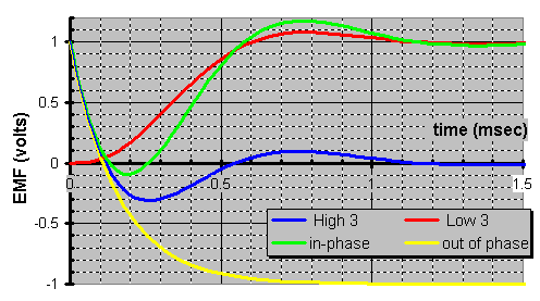
| L0 = R /( 2◊p◊fX ) | C0 = 1 /( 2◊p◊fX◊R ) |
| a1 = 1/2 | a2 = 3/4 | a3 = 3/2 |

|
C2 = C0 / a2 L3 = a3 ◊ L0 |

|
L2 = a2 ◊ L0 C3 = C0 / a3 |
4th order Linkwitz-Riley crossover
This is self-synchronized XO (no polarity need be inverted). It sweeps an entire 360į of phase as it crosses over from an in-phase woofer to an in-phase tweeter. Plus, as a LR XO is has an impedance spike at the XO point where the impedance doubles.
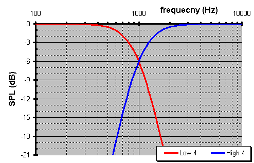
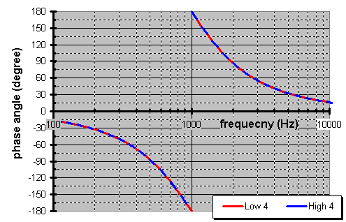
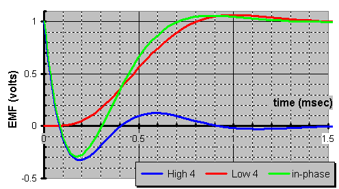
| L0 = R /( 2◊p◊fX ) | C0 = 1 /( 2◊p◊fX◊R ) |
| a1 = 2◊Sqrt[2] | a2 = 2◊Sqrt[2]/3 | a3 = 4◊Sqrt[2]/9 | a4 = 4◊Sqrt[2]/3 |

|
L2 = a2 ◊ L0 C3 = C0 / a3 L4 = a4 ◊ L0 |

|
C2 = C0 / a2 L3 = a3 ◊ L0 C4 = C0 / a4 |
| ORDER | cut-off | phase diff | impedance | Q@fx | SPL@fx | wired |
|---|---|---|---|---|---|---|
| 1st | 6dB/oct | +90į;-270į | flat | Sqrt[½] | -3dB | in-phase |
| 2nd | 12dB/oct | Ī180į | 2X spike | ½ | -6dB | out-of-phase |
| 3rd | 18dB/oct | +270į;-90į | flat | Sqrt[½] | -3dB | either |
| 4th | 24dB/oct | 0į | 2X spike | ½ | -6dB | in-phase |
Notch filters
Time to go full circle. Remember the 1st LRC circuit? How about the voltage divider? Well, weíre about to implement them. What for you ask? Well, some distortion like diaphragm break-up is obtrusive but happens over a very small bandwidth. So, if you install a very high Q LRC circuit the circuit resonance wonít discolor the break-up but will smooth out the sound over this harsh region. You already know what value the resistor will be. It will be the value necessary to dive the voltage. Only now the parallel L & C components short values not within the band (the cap will short out HFs & the coil will short out the LFs).
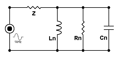
Letís make an arbitrary example where a 10dB spike occurs at 1kHz. The bandwidth is defined by the frequencies f1 & f2 at the mid amplitude (5dB).
| CN = Sqrt[( RN + Z )/ Z] / ( 2◊p◊( f2 - f1 )◊RN ) | LN = 1 /( 4◊p≤◊f1◊f2◊CN ) |
Hereís an example where the f1=800Hz & f2=1250Hz on the 10dB spike @ 1kHz...
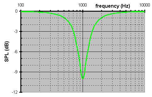
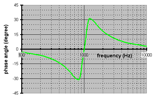
I can hear you now. But, that high Q of a notch will setup an electronic resonance. Trust me. If you need a notch like this you already have a type of mechanical resonance at this frequency as a glimpse at the driverís waterfall plot would illustrate. Thatís why you need the notch in the 1st place. The only difference is this one will be more musical while restoring the acoustic frequency response.